The structure of the subwoofer diagram. Do-it-yourself subwoofer: how to make, theory, diagrams. What is it and why
Here are the technical specifications of the TDA1562 chip:
Supply voltage - 8..18v;
Peak output current - 10A;
Current in rest mode - 0.15A;
Load resistance - 4 ohms;
Output power, at harmonic distortion
-0.03% - 1W
-0.06% - 20W
-0.5% - 55W
-10% - 70W
Voltage gain - 26 dB
Reproducible frequency range - 16 ... 20000 Hz
Input impedance - 10 kOhm
The price of TDA1562 is about 6.
This microcircuit is with a voltage boost, the essence of which is that when playing sound signals, high output power is required for a short period of time, and the rest of the time the output power remains small. Therefore, as long as the output power does not exceed 18W, the device functions as a conventional ULF powered by a 12V source. When the output power exceeds 18W, the internal supply voltage is briefly increased by means of a converter, which includes voltage boost capacitors. Such a solution allows you to get more peak power on the load with a standard power supply of the car's on-board network - 12V.

By closing the contacts, the microcircuit is transferred from standby to working mode and vice versa. The amplifier is not recommended to be connected to subwoofers with built-in filters containing significant capacitances. The TDA1562 chip is quite sensitive to the supply voltage, so do not apply more than 18V to it. develops an output power of 70W at a load of 4 ohms when powered by a unipolar 15V source.

For mounting the microcircuit, use thick wires, as there is a current consumption of up to 10 amperes. This also applies to the wires going to the subwoofer speaker, because even a small increase in line resistance will lead to power losses.

The amplifier chip of a homemade subwoofer must be installed on a heat sink with an area of at least 500 cm2. As a radiator, you can use a metal case or car chassis. Alternatively, you can use forced airflow of the microcircuit with a 12-volt cooler from.

We make the subwoofer case from fiberboard of sufficient thickness - so that there is no rattling and overtones. Outside, we glue it with a soft cloth for vibration absorption. We use standard tulips and springy pedals as connectors.


Two are used to indicate subwoofer modes. Green indicates the supply voltage of 12V to the circuit, and red indicates overloads and protection in the TDA1562


The 12V power supply must be screwed in - to improve contact and reduce losses. Tests of the finished subwoofer showed that the sound is no worse than branded mid-range subwoofers, and it is quite possible to assemble a good bass system in a car with your own hands in just 35 and two evenings. Submitted by - in_sane
Discuss the article HOMEMADE SUBWOOFER
A subwoofer amplifier is an essential part of a good speaker system. Without it, it is impossible to achieve normal reproduction of low frequencies. However, it is not necessary to buy this device: having sufficient knowledge in electronics, you can make it yourself.
How is sound reproduced - and why do you need a subwoofer with an amplifier?
First you need to remember why you need an amp for a subwoofer at all. The subwoofer itself is a separate acoustic element (in other words, a speaker) designed to reproduce low frequencies. It is not a necessary detail: good and large speakers are quite capable of reproducing sounds with a frequency of 20 to 120 Hz on their own. However, such columns have two inevitable drawbacks:
- Dimensions. You can't object to banal physics: the lower the frequency, the larger the area of the sound-emitting element should be. By the way, that is why the ultrasound generator can be designed in the form of a keychain, but for infrasound you will need a device sometimes several meters in size. If we are talking about car acoustics, then two (for stereo sound) such speakers in the cabin usually simply have nowhere to put.
- Price. Good speakers that optimally reproduce all frequencies cost a lot and not everyone can afford it.
WATCH VIDEO
The best way out here is to isolate low frequencies into a separate element that can be placed anywhere. The physiology of human hearing is such that the sounds from the subwoofer are not fixed in the direction, and the stereo sound will not be disturbed.
Subwoofers themselves are divided into two types:
- passive, powered by the audio outputs of the system, like regular speakers;
- active, equipped with their own amplifier, where the playback system only needs to give a signal - and the energy to “build up” the diffuser will come from a separate source.
The first type is good because it does not require additional devices - however, a massive low-frequency diffuser "eats off" a fair amount of power. As a result, either the bass is not reproduced properly, or the high frequencies begin to “fall through” and sound dirty. That is why for high-quality sound it is best to use active-type subwoofers with an amplifier.
Types of amplifiers suitable for installation in a car
In practice, an amplifier for a subwoofer in a car can be one of the following types:
- Mono - feeds one speaker, that is, only the subwoofer itself. The rest of the speakers are content with the signal from the audio output of the radio.
- Two-channel - the energy goes to two regular speakers and one subwoofer.
- Four-channel - supplies two woofers and four conventional speakers.
More complex systems designed for a large number of sounding elements, such as a car
subwoofer power amplifiers are impractical and almost never used.
In addition, you can select the amplifier power for the subwoofer. In relation to the power of the sub itself (RMS), they are divided into the following types:
- Less power. It is not recommended, as it will not allow you to fully use the possibilities of acoustics.
- Equal RMS. Safe for a sub, but not a car one. The fact is that the voltage of a conventional on-board network with 12 volt outputs can vary. If some other electrical devices are turned on while the amplifier is running, the system will easily go into the clip. This term refers to the situation when they try to get more voltage from the amplifier than is in the power system. And a clipped signal is a quick death of the speaker.
- Exceeding RMS. There are some pitfalls here: if you constantly listen to “heavy” music with an abundance of low frequencies at high volume, such an amplifier will also burn the sub. However, with careful use, this option is still the safest.
Is it possible to make a simple amplifier for a subwoofer with your own hands?
Usually, a sound amplifier for a subwoofer is purchased from specialized stores. However, this is not absolutely necessary. With a certain knowledge of electrical engineering and skills in working with a soldering iron, you can assemble almost any design yourself. With the modern availability of microcircuits and transistors, it is not difficult to purchase any parts.
In order to make an amplifier for a subwoofer with your own hands, you will need:
- chip;
- resistors;
- capacitors;
- transistors.
Depending on the circuit used, additional elements may be required (for example, a ready-made or home-made transformer), but these parts should be enough for a simple subwoofer amplifier.
12 volt car amplifier circuit
In order to assemble an amplifier, you must first determine the circuit for it. There are several options here:
The simplest option based on the TDA1562 chip. Its advantages:
- ease of installation;
- low power consumption.
The disadvantage of the circuit is that you cannot draw more than 50 watts of power from it.
A more complex amplifier circuit for a subwoofer is a variant based on the TDA7294. It includes a subwoofer converter and a low-pass filter mounted on a common printed circuit board.
Finally, here is a circuit that allows you to assemble a 1000w subwoofer amplifier based on the TDA2500. Two channels of about a kilowatt each. However, this option is recommended to be used only in extreme cases: in order to use such a powerful amplifier for a subwoofer, you will have to additionally solve power problems.
Finally, a slightly simpler 800w subwoofer amplifier. Here is his power plan:
How to assemble an amplifier?
For reliability and compactness of the assembly, mounting must be done on a printed circuit board. This will require:
- Computer.
- Program "Sprint-layout" (or similar) for calculation and design of boards.
- Laser printer.
- Foil textolite.
- Ferric chloride solution.
The sequence of actions here will be as follows:
- The program creates a circuit board.
- The board is printed using a laser printer. It is highly advisable to use photo paper and a branded cartridge - refilled ones may have too low toner density. It should look something like this:
- The resulting pattern is carefully cut out along the contour and superimposed on the textolite blank. Before this, the workpiece must be sanded with fine sandpaper (to remove oxides) and degreased with acetone. Then a sheet of paper laid down with a pattern is ironed with a hot iron. This is the most important operation, the quality of the board depends on it. With proper work, you will get a workpiece with a toner pattern applied to it. The temperature must be set to the maximum so that the toner melts again and sticks to the foil.
- The workpiece that has cooled down after the iron is soaked in water, after which the soaked paper is carefully removed.
- The drawing is checked. If some elements are not printed, they can be drawn with a permanent marker. However, you should not abuse this: the marker is not as reliable as the toner.
- Then the workpiece is pickled in ferric chloride. The result is a pure textolite with copper, preserved only where it was protected by a layer of toner or marker.
On the resulting board, it is already possible to mount a microcircuit and other parts in accordance with the chosen design. But before that, you need to decide on nutrition. Here again, a computer and a program for calculating transformers are required: it is necessary to convert the on-board 12 V to at least 80. After the calculation, the winding is mounted on the core with the insulation of each layer. A great option for a homemade car subwoofer is to use old TV transformers with the appropriate recalculation of the winding.
WATCH VIDEO
Lastly, the low-pass filter is mounted. Without it, high-frequency signals will go to the sub - and then the use of the subwoofer itself is pointless. The filter is mounted in the same way as the rest of the amplifier, and after that you can proceed to testing on the on-board network and radio.
Important: when testing the amplifier, you must connect it only through resistors and an incandescent lamp! Otherwise, there is a risk of burning the parts even before the design is ready.
Installing the amplifier in the case and using wires
After the electronic part is ready, you need to think about the case and wires for power and signals. There are many options here depending on what materials are available. In particular, you can use:
- plywood;
- aluminum profile;
- fiberboard, etc.
Separately, you need to take care of the wires. They must be well-insulated to avoid electromagnetic interference and signal distortion.
In this article, we will see how to make a subwoofer with our own hands, without delving into the bowels of electroacoustics, without resorting to complex calculations and delicate measurements, although some will still have to be done. "Without much difficulty" does not mean "a blunder on a brick, drive, grandma, mogarych." These days, it is possible to model very complex acoustic systems (AS) on a home computer; see the link at the end for a description of this process. But working with a ready-made device on a whim gives something that you can’t get by any reading and viewing - an intuitive understanding of the essence of the process. In science and technology, pen-tip discoveries are rare; most often, the researcher, having gained experience, "inside" begins to understand what's what, and even then he looks for mathematics suitable for describing the phenomenon and deriving design engineering formulas. Many great ones recalled their first unsuccessful experiences with humor and pleasure. Alexander Bell, for example, at first tried to wind the coils for his first telephone with a bare wire: he, a musician by education, simply did not yet know that the wire under current should be insulated. But Bell did invent the telephone.
About computer calculations
Do not think that JBL SpeakerShop or other acoustic calculation program will give you the only possible most correct option. Computer programs are written according to well-established proven algorithms, but non-trivial solutions are impossible only in theology. “Everyone knows that this is not the way to do it. There is a fool who does not know this. He is the one who makes the invention.”- Thomas Alva Edison.
SpeakerShop appeared not so long ago, this application was developed very thoroughly and the fact that it is used very actively is an absolute plus for both developers and amateurs. But in some ways, the current situation with him is similar to the story of the first photoshops. Who else used Windows 3.11, remember? - then they just went crazy with the processing of pictures. And then it turned out that in order to take a good picture, you still need to be able to take pictures.
What is it and why?
A subwoofer (simply - a subwoofer) in a literal translation sounds curious: a podgavkivatel. In reality, this is a bass (low-frequency, woofer) speaker that reproduces frequencies below approx. 150 Hz, in a special acoustic design, a box (box) of a rather complex device. Subwoofers are also used in everyday life, in high-end floorstanding speakers and inexpensive desktop speakers, built-in and in cars, see fig. If you manage to make a subwoofer that correctly reproduces bass, you can safely take on, because. low-frequency reproduction is perhaps the fattest of the whales on which all electroacoustics stands.

It is much more difficult to make a compact low-frequency speaker link than midrange and high-frequency (mid- and high-frequency), firstly, due to an acoustic short circuit, when sound waves from the front and rear radiating surfaces of the speaker (loudspeaker head, GG) cancel each other out: LF waves are meters, and without proper acoustic design of the GG, nothing prevents them from immediately converge in antiphase. Secondly, the spectrum of sound distortion at low frequencies extends far into the best audible region of the midrange. In essence, any broadband speaker is a low-frequency link, in which midrange and high-frequency emitters are built. But from the point of view of ergonomics, an additional requirement is imposed on the subwoofer: the subwoofer for the home should be as compact as possible.
Note: all types of acoustic design of the LF GG can be divided into 2 large classes - some dampen the radiation from the rear of the speaker, the second turn it in phase by 180 degrees (turn the phase) and re-radiate from the front. A subwoofer, depending on the properties of the GG (see below) and the required type of its amplitude-frequency characteristic (AFC), can be built according to a scheme of one class or another.
A person distinguishes the direction to sounds below 150 Hz very poorly, so in an ordinary living room a sub can be placed anywhere in general. MF-HF speakers (satellites) acoustics with a subwoofer are very compact; their location in the room can be chosen optimally for this room. Modern housing with an excess of space and good acoustics, to put it mildly, does not differ, and it is not always possible to “stick” at least a couple of good broadband speakers in it correctly. Therefore, making a subwoofer on your own allows you not only to save a very substantial amount of money, but still get a clean, true sound in this Khrushchev, Brezhnevka or modern new building. The subwoofer is especially effective in full surround sound systems, as putting 5-7 columns on a full page each is too much for the most “fancy” users.
bass
Bass reproduction is not only technically difficult. The narrow, in general, low-frequency section of the entire spectrum of sound waves is heterogeneous in its psychophysiological effects and is divided into 3 areas. To choose the right bass speaker and make a subwoofer box with your own hands, you need to know their boundaries and meaning:
- Upper bass (UpperBass) - 80-(150 ... 200) Hz.
- Medium bass or midbass (MidBass) - 40-80 Hz.
- Deep bass or sub-bass (SubBass) - below 40 Hz.
top
middle
On midbass, the main task when creating a subwoofer is to ensure the highest return of the GG, the given shape of the frequency response and its maximum uniformity (smoothness) in the minimum volume of the box. Frequency response, close to rectangular in the direction of lower frequencies, gives a powerful, but harsh bass; Frequency response, evenly falling - clean and transparent, but weaker. The choice of one or the other depends on the nature of the listened to: rockers need a “angrier” sound, and more gentle for classics. In both cases, large dips and bursts in the frequency response spoil the subjective perception with formally identical sound technical parameters.
Depth
The subbass has a decisive influence on the timbre (color) of the sound of musical instruments only for wind organs in halls specially built for them. Strong sub-bass components are characteristic of the sounds of natural and man-made disasters, strong explosions and the voices of certain animal species (lion's roar). Over 90% of people either do not hear subbass at all, or hear it indistinctly. For example, if the sounds of a tropical hurricane and a nuclear explosion are fundamentally different in nature and are filtered out from everything except for sub-bass, then hardly anyone can tell from them what is really going on there. Therefore, a home subwoofer is almost always optimized for mid-bass, and the rest of the sub-bass, which happens, masks the room's own noise. For what it, by the way, is very suitable and how it is very useful.Subbass in the car
The effect of noise masking is especially needed in a cramped and noisy car interior, so auto subwoofers are optimized for sub-bass. Sometimes for the sake of this, Hi-Fi lovers at speed give the entire trunk to the subwoofer, putting there 15 "-18" monster speakers with 150-250 watts of peak power, see fig. However, a quite decent subwoofer in a car can be made without sacrificing useful volume in the back, see below.

Note: the peak power of the speaker is often identified with the noise, which is not true. At peak power, the sound is distorted, but still distinct, i.e. distinguish in meaning. Noise power is defined as that which a speaker can operate for a certain amount of time (usually 20 minutes) without burning out or being mechanically damaged. In this case, the sound is most often incoherent wheezing, which is why such power is called noise. But in some types of acoustic design, the noise power of the speaker may be lower than the peak, see below.
What speaker do you need?
A complete calculation of the acoustic design is carried out according to the so-called. Thiel-Small parameters (PTS). Since we decided to spend time and effort tuning the subwoofer, we only need the full quality factor of the head at its own resonant frequency Qts, because it is on it that the optimal variant of acoustic design is selected. Depending on the value of Qts, the dynamics are divided into 4 groups:
- Qts<0,5 – «безразличные» сверхнизкодобротные. Очень дорогие, очень низкая отдача, но способны воспроизводить подбасы вплоть до 20-15 Гц. Настройка сабвуфера с такими без звукомерной камеры и специальной измерительной техники невозможна, т.к. резонансный пик не выражен.
- 0,5
- 0,7
- Qts>1 - high quality. High return, low price, harsh sound in suboptimal design. It is difficult to get a smooth frequency response. Compact, available in diameters (down) up to 6” (155 mm). Optimal for a desktop subwoofer or a TV (not a home theater!).
- 0,7
measurements
In speaker manufacturer's specifications, Qts may be referred to as Qp or simply Q, but it is not always present there, and public databases like WinISD are full of errors. Therefore, we will most likely have to determine the value of Qts at home.
Preparation
First of all, we select and prepare a room for acoustic measurements. It should have as many curtains, curtains, carpets on the floor and walls, upholstered furniture as possible. Rigid horizontal surfaces (table) need to be covered with something fluffy; It will not be superfluous to throw more pillows everywhere. The corners distort the sound field especially strongly, incl. hard furniture with walls, they need to be curtained with something, for example, with clothes on hangers. Next, we connect long wires to the speaker and hang them in the geometric center of the ceiling (under the chandelier, if any) with the front side of the diffuser down at a height of 2/3 of the ceiling height from the floor.

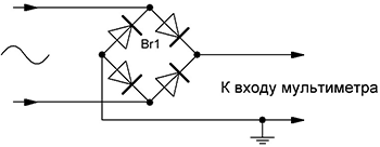
Now you need to assemble the measurement circuit, as shown at the top in Fig. We still need the lower circuit to measure the impedance (impedance) of the speaker Z. This one differs from the measuring circuit usually used by amateurs without a transformer with quite professional accuracy: in common circuits on bridge diodes, approx. 1.5 V even with tester input resistance of 10 MΩ. The operation of this circuit is based on the fact that the impedance of the transformer and R2, on the one hand, is much greater than the impedance of the GG; on the other hand, it is much less than the output impedance of the audio frequency power amplifier, and on the fact that the lousiest digital multitester at the 200 mV limit has an input impedance of more than 1 MΩ. However, if the measurement signal is supplied from an audio frequency generator (AFG) with a standard 600 ohm output, this circuit is not suitable for measuring Z.
Procedure
From the computer with the GZCH emulation program, the measuring signal is fed from the output of the sound card. You need to “drive” it within 20-100 Hz at first with a discrete (step) of 10 Hz. If the GG resonance is not visible, it is unsuitable for a subwoofer. Or the seller shamelessly deceived you by selling for 100 rubles. indifferent GG at the price of $200.

When the boundaries of the resonant peak are determined, we “pass” it already with a discrete of 1 Hz and build the frequency response. If the GG is high- or medium-quality closer to the upper limit of Qts, you get a graph like the one in pos. I fig. In this case:
- According to the f-le (1) on pos. II find U(F1,F2);
- According to the schedule, we find F1 and F2;
- Using f-le (2), we check whether the calculated frequency of natural resonance in free space F's coincides with the measured Fs. If the discrepancy is more than 2-3Hz, see below;
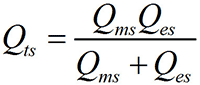
- Using f-le (3) we find the mechanical quality factor Qms, then f-le (4) electrical Qes and, finally, f-le (5) the required total quality factor Qts.
If the quality factor of the GG is closer to low or such that it is generally good, the resonance curve will be noticeably asymmetric, and its peak will be flat, blurry, pos. III, or the check on f-le (2) will not converge even with repeated measurements. In this case, according to the graph, we determine the points of the greatest slope of the tangents to the concave "wings" of the A1 and A2 peaks; mathematically, in them the second derivative of the function describing the resonance curve reaches a maximum. For Umax then we take, as before, its value at the top of the peak, and for Umin - calculated from the f-le at pos. III new value U(F1,F2).
System Structure
Have you measured? Is the speaker suitable? Do not rush to choose a design. First you need to choose a block diagram of the entire sound system, because. its electronic part can bear a share of the cost no less than a good bass speaker. A sound system with a subwoofer can be built according to one of the following. diagrams, see fig.

Note: the equalizer and the infra-low frequency Finch filter (rumble filter) in all circuits are switched on before the inputs of the stereo channels.
Pos. 1 – system with passive power filtering. Plus - you don't need a separate bass amplifier, it connects to any UMZCH. Huge disadvantages, the first, mutual electric leakage of channels in the subwoofer over the midrange: for LC filters that reduce it to an acceptable value, you will need a decent case, which, in order to buy their components, will first have to be filled with about a third of money (in 100 ruble bills). Secondly, the output resistances of the low-pass filters of the low-pass filter, together with the input GG of the speaker, form a tee, and each UMZCH channel will theoretically spend a quarter of the power on heating its neighbor with its low-pass filter. Really - more, because. on power and losses in filters are significant. However, the power filtered system is applicable to small power subwoofers with independent sound drivers, see below.
Pos. 2 - passive filtering into a separate bass UMZCH. There are no power losses, the mutual influence of the channels is weaker, because characteristic resistances of filters are kilo-ohms and tens of kilo-ohms. Currently, it is practically not used, because. It turns out to be much easier and cheaper to assemble an active filter on microcircuits than to wind passive coils.
Pos. 3 – active analog filtering. The channel signals are added by a simple resistor adder, fed to the analog active low-pass filter, and from it to the bass UMZCH. Channel interference is negligible and imperceptible under normal listening conditions, the cost of components is low. The optimal circuit for a homemade subwoofer for a novice amateur.
Pos. 4 - full digital filtering. The channel signals are fed to the splitter R, which divides each of them into at least 2 equal to the original ones. One signal from a pair is fed to the MF-HF UMZCH (possibly directly, without a high-pass filter), and the rest are combined in adder C. The fact is that with resistor addition at the lower frequencies of the midbass and in the subbass, electrical interaction of signals in the low-pass filter is possible, several distorting the overall bass. In the adder, the signals are added in a digital or analog way, excluding their mutual influence.
From the adder, the general signal is fed to a digital low-pass filter with built-in analog-to-digital (ADC) and digital-to-analog (DAC) converters, and from it to the bass UMZCH. The sound quality and channel isolation are the highest possible today. The cost of microcircuits for this entire economy turns out to be feasible, but working with ICs already requires some amateur radio experience, and even more - if you do not buy a ready-made set (which is much more expensive), and the system components are selected independently.
Decor
On fig. the most commonly used acoustic design schemes for home subwoofers are given. Labyrinths, horns, etc. do not meet the requirements of compactness. Beginners prefer schemes in green, doable ones in yellow, and unsuitable ones in red. Who is more experienced may be surprised: the 6th bandpass is for dummies? No worries, this great bass acoustic on trumpets can be set up over the weekend. If you know how.

Shield
Making a subwoofer in the form of an acoustic screen (shield, pos. 1) at home is feasible if the GGs are built into the wall sheathing, because their sizes are commensurate with the lengths of sub-bass waves. Hence the dignity - there are no problems with the sub-bass, as long as the speakers pull it. Another is the utmost compactness, the subwoofer does not occupy usable space at all. But there are also serious disadvantages. The first is a large amount of construction work. The second - the acoustic screen does not affect the frequency response of the GG. “Humpbacked” will sing like that, so you can only put expensive low-quality and indifferent speakers on the shield. A sub-minus, so to speak - their return is small and the shield is not able to increase it in any way.
closed box
A huge plus of a closed box (pos. 2) - deep damping of the GG; for inexpensive, high-response, high-quality speakers, this is the only acceptable type of acoustic design. But this plus entails a minus: with deep damping, the noise power of the GG often turns out to be lower than the peak, especially for expensive powerful heads. The coil is already smoking, but the wheezing is still not audible. An overload indicator is needed, but the simplest ones without a separate power supply distort the signal.
An equally fat plus is an extremely smooth, smoothly falling frequency response and, as a result, the clearest and most lively sound. For this reason, high-end powerful high-quality GGs are produced specifically for installation in closed boxes or 4th order bandpasses (see below).
Minus - of all speakers of equal volume, a closed box has the highest lowest reproducible frequency, because. it increases the resonant frequency of the speaker and is not able to increase its output at frequencies below it. Those. in terms of compactness, the subwoofer in a closed box passes with a big stretch. To some extent, this disadvantage can be reduced by filling the box with padding polyester: it perfectly absorbs the energy of sound waves. The thermodynamic process in the box then changes from adiabatic to isothermal, which is equivalent to an increase in its volume by 1.4 times.
Another significant disadvantage is that only a passive subwoofer can be made in a closed box, because. the electronics in it are very hot even placed in a fenced off compartment. If you come across old AC 10MAS-1M, drive them at half power for half an hour and touch the case with your hand - it will be warm.
FI
Note: FI is equivalent in everything to a passive radiator (PI) - instead of a pipe with a port, they put a bass speaker without a magnetic system and with a weight instead of a coil. There are no “non-tuning” methods for calculating PI, therefore, in industrial production, PI is a rare exception. If you have a burnt bass speaker lying around, you can experiment - the setting is done by changing the weight of the load. But keep in mind - it is better not to make active PI for the same reason as a closed box.
About deep cracks
Acoustics with deep slots (pos. 4, 6, 8-10) are sometimes identified with PHI, sometimes with a labyrinth, but in fact it is an independent type of acoustic design. The advantages of a deep gap are many:
There is only one drawback to a deep gap, and that is for beginners: it is not customizable after assembly. As it is done, so it will sing.
About antiacoustics

bandpasses
BandPass in translation is the passage of the band, the so-called speakers without direct emission of sound into space. This means that bandpass speakers do not emit midrange due to its internal acoustic filtering: the speaker is placed in a partition between resonating cavities, ports of pipes or deep slots that communicate with the atmosphere. Bandpass - acoustic design specific to subwoofers and does not apply to completely separate speakers.
Bandpasses are divided according to the magnitude of the order, and the order of the bandpass is equal to the number of its own resonant frequencies. High-Q GGs are placed in bandpasses of the 4th order, where it is easy to organize acoustic damping (pos. 5); low- and medium-quality - into bandpasses of the 6th order. Contrary to popular belief, there is no tangible difference in sound quality between those and those: already on the 4th order, smoothing of the frequency response at low frequencies up to 2 dB or less is achieved. The difference between them for an amateur is mainly in the complexity of the settings: to fine-tune the 4th bandpass (see below), you will have to move the partition. As for bandpasses of the 8th order, they have 2 more resonant frequencies due to the acoustic interaction of the same 2 resonators. Therefore, the 8th bandpass is sometimes called the 6th order bandpass of class B.
Note: idealized frequency response at low frequencies for some types of acoustic design are shown in fig. red. The green dotted line is the ideal frequency response from the point of view of the psychophysiology of hearing. From where it can be seen that there is still enough and enough work in electroacoustics.

Amplitude-frequency characteristics of the same loudspeaker head in different acoustic design
Auto subwoofers
Car subwoofers are usually placed either in the cargo compartment, or under the driver's seat, or behind the back of the rear seat, pos. 1-3 in fig. In the first case, the box takes up useful volume, in the second case the subwoofer works in difficult conditions and can be damaged by feet, in the third case, not every passenger will be able to endure a powerful bass right next to their ears.

Recently, a car subwoofer is increasingly being made of the stealth type, built into the rear wing niche, pos. 4 and 5. Sufficient sub-bass is achieved by using special auto-speakers with a diameter of 12 ”with a rigid cone, little susceptible to the membrane effect, pos. 5. How to make a subwoofer for a car by molding a wing niche, see next. video.
Video: do-it-yourself car subwoofer "stealth"
It just doesn't get easier
A very simple subwoofer that does not require a separate bass amplifier can be made according to a scheme with independent sound emitters (IS), see fig. In fact, these are two channel woofers GG, placed in a common long case, installed horizontally. If the length of the box is comparable to the distance between the satellites or the width of the TV screen, the "spreading" of the stereo is hardly noticeable. If listening is accompanied by viewing, then it is completely imperceptible due to involuntary visual correction of the localization of sound sources.

According to the scheme with independent OUTs, you can make an excellent subwoofer for a computer: a box with speakers is placed in the far upper corner under the tabletop. The cavity below it is a resonator tuned to a very low frequency, and an unexpectedly good sub-bass cuts through from a small box.
FI for a subwoofer with independent OUT can be calculated in the speaker shop. In this case, the equivalent volume Vts is taken twice as much against the measured one, the resonant frequency Fs is 1.4 times lower, and the total quality factor Qts is 1.4 times greater. The material of the box, as elsewhere, is MDF from 18 mm; for subwoofer power from 50 W - from 24 mm. But it is better to place the speakers in a closed box, in this case it can be done without calculation: the length inside is taken at the installation site ranging from 0.5 m (for a computer) to 1.5 m (for a large TV). The cross section of the box inside is determined based on the diameter of the speaker cone:
- 6 "(155 mm) - 200x200 mm.
- 8 "(205 mm) - 250x250 mm.
- 10" (255 mm) - 300x300 mm.
- 12" (305 mm) - 350x350 mm.
In the worst case (under-table computer subwoofer with 6" speakers), the volume of the box will be 20 liters, and the equivalent with filling - 33-34 liters. With an UMZCH power of up to 25-30 W per channel, this is enough to get a decent midbass.
Filters
LC filters in this case are better to use type K. They need more coils, but in amateur conditions this is not essential. K-filters have low attenuation in the stopband, 6 dB / oct per link or 3 dB / oct per half link, but a completely linear phase response. In addition, when operating from a voltage source (which is UMZCH with great accuracy), the K-filter is not very sensitive to changes in the load impedance.
At pos. 1 fig. schemes of K-filter links and calculation formulas for them are given. R for LF GG is taken equal to its impedance Z at the cutoff frequency of the LPF 150 Hz, and for the HPF equal to the impedance of the satellite z at the cutoff frequency of the HPF 185 Hz (formula in pos. 6). Z and z are determined according to the scheme and formula in fig. above (with measurement schemes). Working diagrams of filters are given in pos. 2. If you prefer to buy capacitors rather than winding coils, exactly the same parameters can be made up of P-links and half-links.

Data and diagrams for the manufacture of filters for a simple subwoofer with independent radiators
The attenuation of the low-pass filter in the stopband is 18 dB / oct, and the high-pass filter is 24 dB / oct. Such a frankly non-trivial ratio is justified by the fact that the satellites are unloaded from the bass and give a cleaner sound, and the rest of the bass reflected from the HPF is sent to the bass speakers and makes the bass deeper.
Data for the calculation of filter coils are given in pos. 3. They need to be arranged mutually perpendicular because K-filters work without magnetic coupling between the coils. When calculating, they are set by the dimensions of the coil and, according to the inductance found in the order of calculating the filter, the number of turns is determined. Then, using the stacking factor, find the diameter of the wire in the insulation, it should be at least 0.7 mm. It turns out less - we increase the size of the coil and recalculate.
Setting
Setting up this subwoofer comes down to equalizing the volumes of the woofers and satellites, respectively. cutoff frequencies. To do this, first prepare the room for acoustic measurements, as described above, and a tester with a bridge and a transformer. Next, you need a condenser microphone. For a computer one, you will have to make some kind of microphone amplifier (MUS) with a bias applied to the capsule, because. a conventional sound card cannot simultaneously receive a signal and emulate a GZCH, pos. 4. If there is a condenser microphone with a built-in MCC, at least an old MKE-101, excellent, its output is connected directly to the primary (smaller) winding of the transformer. The measurement procedure is simple:
- The microphone is fixed opposite the geometric center of the satellites at a horizontal distance of 1-1.5 m.
- The subwoofer is disconnected from the UMZCH and a 185 Hz signal is applied.
- Record the voltmeter readings.
- Without changing anything in the room, they turn off the satellites, turn on the sub.
- A 150 Hz signal is applied to the UMZCH, the readings of the tester are recorded.
Now you need to calculate the equalizing resistors. Equalize the volume by muffling the louder links in a series-parallel circuit (pos. 5), because. it is necessary to keep the previously found values of Z and z unchanged in absolute value. Calculation formulas for resistors are given in pos. 6. Power Rg - not less than 0.03 of the power of the UMZCH; Rd - any from 0.5 W.
Too simple
Another option for a simple, but already real subwoofer is with a paired woofer GG. Pairing woofers is a very effective way to upscale their sound. The design of the subwoofer on a pair of old 10GD-30 is given in fig. below.

The design is very perfect, bandpass of the 6th order. Bass amplifier - on TDA1562. You can use other high-quality GGs with a relatively small diffuser stroke, then you may have to make adjustments by selecting the length of the pipes. It is produced at control frequencies of 63 and 100 Hz next. way (control frequencies are not resonant speakers!):
- Prepare the room, microphone and instruments as described above.
- Served on UMZCH alternately 63 and 100 Hz.
- Change the length of the pipes, achieving a difference in voltmeter readings of no more than 3 dB (1.4 times). For gourmets - no more than 2 dB (1.26 times).
The tuning of the resonators is interdependent, so the pipes must be moved according to: the short one is pushed out, by the same amount, in proportion to its original length, the long one is pushed in. Otherwise, you can completely upset the system: the peak of the optimum setting for the 6th bandpass is very sharp.
- A dip between 63 and 100 Hz - the baffle must be moved towards the larger resonator.
- Dips on both sides of 100 Hz - the baffle is shifted towards the smaller resonator.
- Surge closer to 63 Hz - you need to increase the diameter of the long pipe by 5-10%
- A surge closer to 100 Hz is the same, but for a short pipe.
After any of the fitting procedures, the subwoofer is reconfigured. For its convenience, a complete assembly on glue is not done at first: the partition is tightly smeared with plasticine, and one of the side walls is placed on double-sided tape. Make sure there are no gaps!

Tubes for resonators
Ready-made bent pipes for acoustics are sold in music and radio stores. You can make a telescopic acoustic pipe with your own hands from scraps of plastic or cardboard pipes. In both cases, 2 pieces of fishing line must be firmly glued across the inner mouth: one is tight, the other is a loop protruding outward, see fig. on right. If the pipe needs to be moved apart, a pencil is pressed on a tight fishing line, etc. If shortened - pull the loop. Tuning a resonator with a pipe is thus accelerated many times over.
Powerful 6th order
Drawings of the bandpass of the 6th order under 12 ”GG are given in fig. This is already a solid floor structure for power up to 100 watts. It is configured like the previous one.

Subwoofer drawings 6th order bandpass for 12″ speaker
4th order
Suddenly, a 12 ”high-Q GG will be at your disposal, it will be possible to make a 4th-order bandpass of the same quality, but more compact, see Fig. dimensions in cm. However, setting it up will be much more difficult, because. instead of manipulating the tube of a larger resonator, you will have to immediately move the baffle.

Subwoofer bandpass 6th order for 12″ speaker
Electronics
The bass UMZCH for a subwoofer is subject to the same as for filters, the requirement for full linearity of the phase response. The UMZCH, made according to the bridge circuit, satisfies it, it also reduces the nonlinear distortions of the integral UMZCH with a non-complementary output by an order of magnitude. UMZCH for a subwoofer with a power of up to 30 W can be assembled according to the scheme in pos. 1 rice; 60-watt according to the scheme in pos. 2. It is convenient to make an active subwoofer on a single chip of a 4-channel UMZCH TDA7385: a couple of channels are sent to the satellites, and the other two are switched on by a bridge circuit to the subwoofer, or, if it is with independent OUT, they are allowed to go to the woofers. The TDA7385 is also convenient in that it has common inputs for the St-By and Mute functions for all 4 channels.

According to the scheme in pos. 3 makes a good active subwoofer filter. The amplification of its normalizing amplifier is regulated by a variable resistor of 100 kOhm over a wide range, so in most cases the rather dreary procedure for equalizing the volumes of the subwoofer and satellites disappears. Satellites in this version are included without HPF, and potentiometers for presetting the volume with slots for a screwdriver are built into the MF-HF amplifiers.
You might want to design a slotted subwoofer from scratch instead of fiddling with reconfiguring prototype subwoofers to fit your speaker. In this case, follow the link: //cxem.net/sound/dinamics/dinamic98.php . The author, we must give him his due, was able to explain at the level “for luminous dummies” how to calculate and make a high-class subwoofer using modern software. However, in a big case, not without a miss, therefore, when studying the source, keep in mind:

And still…
Making a sub yourself is exciting, useful for developing intelligence and skill, besides, a good bass speaker costs one and a half times cheaper than a pair of a lower class. However, at control auditions, both seasoned experts and casual listeners "from the street", all other things being equal, clearly prefer sound systems with full channel separation. So think about it first: won’t you still have a couple of separate columns in your hands and wallet?
It all started with the fact that a year and a half ago I bought a twelve-inch woofer in order to assemble a car subwoofer. But there was not enough time, and the speaker stale in my apartment. And now, a year and a half later, I finally decided to assemble, but not a car, but an active home subwoofer. In this article I will describe step-by-step instructions for calculating and assembling subwoofers of this type.
1. Calculation and design of the case (box) of the subwoofer
To calculate the subwoofer enclosure, we need:
- Thiel-Small parameters for loudspeaker,
- Program for calculating acoustic design
1.1 Measurement of the Thiel-Small parameters for a loudspeaker
Usually these parameters are indicated by the manufacturer in the loudspeaker's passport or on their website. But now most of the loudspeakers sold in the markets (including my loudspeaker) do not have these parameters specified or do not correspond to them (despite numerous attempts, I have not been able to find my speaker on the Internet, and the Thiel-Small parameters have already and there was no question.) Therefore, we will have to measure everything ourselves.
For this we need:
- Computer or laptop with a GOOD (that is, with a linear frequency response) sound card,
- A software sound generator that uses the headphone output of a sound card (I personally like the program,
- AC voltmeter with the ability to measure voltage of the order of 0.1 mV,
- drawer with phase inverter,
- Resistor 150-220 Ohm,
- Connectors, wires, etc……..

1.1.1. First, let's check the linearity of the frequency response of the sound card. There are a large number of programs that automatically measure the frequency response in the range of 20-20000 Hz (when the headphone output is connected to the microphone input of the sound card). But here I will describe a manual method for measuring the frequency response in the range of 10-500Hz (only this range is important for measuring the Til Small parameters of a low-frequency radiator). If an AC voltmeter with the ability to measure voltage of the order of 0.1 mV is not at hand, do not worry, you can use a regular inexpensive multimeter (Tester). Typically, such multimeters measure AC voltage with an accuracy of 0.1V and DC voltage with an accuracy of 0.1 mV. To measure an alternating voltage of the order of several mV, you just need to put a diode bridge in front of the multimeter input and measure direct voltage in the voltmeter mode in the range up to 200mV.
First, connect a voltmeter to the headphone output (Either to the right or to the left channel).

Turn off all sound effects and equalizers, open the speaker properties and set the volume level to 100%.

Open the program, press “Options”, in “Tone Interval” select “Frequency”, and set the step to 1Hz.

Close "Options", set the volume level to 100%, set the initial frequency to 10Hz and press "Play". With the “+” button, we begin smoothly, in 1 Hz steps, to increase the generator frequency to 500 Hz.

At the same time, we look at the voltage value on the voltmeter. If the maximum amplitude difference is within 2dB (1.259 times), then such a sound card is suitable for measuring speaker parameters. For me, for example, the maximum value was 624mV, and the minimum was 568mV, 624/568=1.09859 (0.4dB), which is quite acceptable.
1.1.2. Let's move on to the long-awaited Thiel-Small parameters. The minimum parameters by which you can calculate and design acoustic design (in this case, a subwoofer) is:
- Resonance frequency (Fs),
- Total electromechanical quality factor (Qts),
- Equivalent volume (Vas).
For a more professional calculation, even more parameters will be needed, such as mechanical quality factor (Qms), electrical quality factor (Qes), sensitivity (SPL), etc.
1.1.2.1. Determining the resonant frequency (Fs) of a loudspeaker.
We collect such a scheme.


The speaker should be in free space as far as possible from the walls, floor and ceiling (I hung it from a chandelier). We open the NCH Tone Generator program again, insist on the volume as described above, set the initial frequency to 10Hz and begin to gradually increase the frequency in 1Hz steps. At the same time, we again look at the value of the voltmeter, which will first increase, reach the maximum point (Umax) at the natural resonance frequency (Fs), and begin to decrease to the minimum point (Umin). With a further increase in frequency, the voltage will gradually increase. The graph of the dependence of voltage (active resistance of the speaker) on the frequency of the signal looks like this.

The frequency at which the voltmeter value is maximum is the approximate resonant frequency (at a step of 1 Hz). To determine the exact resonant frequency, it is necessary in the region of the approximate resonant frequency to change the frequency in steps no longer by 1 Hz, but by 0.05 Hz (accuracy 0.05 Hz). We write down the resonant frequency (Fs), the minimum value of the voltmeter (Umin), the value of the voltmeter at the resonant frequency (Umax) (in the future they will be useful for calculating the following parameters).
1.1.2.2.
Determination of the total electromechanical quality factor (Qts) of a loudspeaker.
Find UF1,F2 using the following formula.
![]()
By changing the frequency, we achieve the values of the voltmeter corresponding to the voltage UF1, F2. There will be two frequencies. One is below the resonant frequency (F1), the other is above (F2).

You can check the correctness of the calculations with this formula.

If the difference between Fs' and Fs does not exceed 1 Hz, then you can safely continue measurements. If not, then you need to do everything first. We find the mechanical quality factor (Qms) using this formula.

The electrical quality factor (Qes) is found using this formula.

Finally, we determine the total electromechanical quality factor (Qts) using this formula.
1.1.2.3. Determine the equivalent volume (Vas) of a loudspeaker.
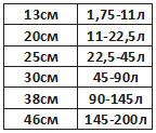
To determine the exact equivalent volume, we need a prefabricated, durable, sealed bass reflex box with a hole for our speaker.

The volume of the box depends on the diameter of the speaker, and is selected according to this table.
We fix the speaker to the box and connect it to the circuit described above (Fig. 9). Again, open the NCH Tone Generator program, set the initial frequency to 10Hz and use the “+” button to start smoothly, in 1Hz steps, to increase the generator frequency to 500Hz. At the same time, we look at the value of the voltmeter, which again begins to increase to the frequency FL, then decrease, reaching the minimum point at the frequency of the phase inverter (Fb), increase again and reach the maximum point at the frequency FH, then decrease and slowly increase again. The graph of the dependence of voltage on the frequency of the signal has the form of a two-humped camel.


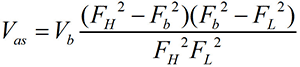
And finally, we find the equivalent volume (Vas) using this formula (where Vb is the volume of the box with the phase inverter).
We repeat all our measurements 3-5 times and take the arithmetic mean of all parameters. For example, if we got the Fs values, respectively, 30.45Hz 30.75Hz 30.55Hz 30.6Hz 30.8Hz, then we take (30.45+30.75+30.55+30.6+30.8)/5= 30.63Hz.
As a result of all my measurements, I received the following parameters for my speaker:
- Fs=30.75Hz
- Qts=0.365
- Vas=112.9≈113 L
1.2. Modeling and calculation of the subwoofer case (box) using the JBL Speakershop program.
There are several options for acoustic design, of which the following options are most common.
- Vented box-box with phase inverter,
- Band-pass 4th, 6th and 8th order,
- Passive radiator - a box with a passive radiator,
- Closed box - a closed box.

The type of acoustic design is selected based on the Thiel-Small parameters of the loudspeaker. If Fs/Qts<50, то такой громкоговоритель можно использовать исключительно в закрытом оформлении, если Fs/Qts>100, then exclusively in Vented box or Band-pass or Closed box. If 50
First, download and install the program. This program is written for Windows XP and does not work on Windows 7. To make the program work on Windows 7, you need to download and install the Windows Virtual PC-XP Mode virtual machine (you can download it from the official Microsoft website), and run the installation of JBL Speakershop through it. You also need to open JBL Speakershop through a virtual machine. After opening the program, we see this interface.

Press “Loudspeaker” and select “Parameters--minimum”, in the open window we write, respectively, the value of the resonant frequency (Fs), the value of the equivalent volume (Vas), the value of the total electromechanical quality factor (Qts) and press “Accept”.

At the same time, the program will offer two optimal (with the most even frequency response) options, one in a closed design (Closed box), the other in a Vented box (box with a phase inverter). Press “plot” (both in the Vented box and in the Closed box) and look at the frequency response graph. We choose the design, the frequency response of which is most suitable for our requirements.

In my case, this is the Vented box, because at low frequencies (20-50Hz), the Closed box has a much larger amplitude drop than the Vented box (Figure above).
If the volume of the box suits you optimally, then you can build a box with such a volume and enjoy the sound of the subwoofer. If not (with too large volumes), then you need to set your own volume (the closer to the optimal volume, the better) and calculate the optimal tuning frequency of the phase inverter.

To do this, in the Vented box area, click “Custom”, in the window that opens, write your volume of the box, click “Optimum Fb” (in this case, the program will calculate the optimal tuning frequency of the phase inverter, at which the frequency response of the acoustic design will be the most linear) and then “Accept”.

Press “Box” and select “Vent…”, in the window that opens, in the “Custom” area, write the diameter of the pipe (Dv), which we will use as a phase inverter. If we use two phase inverters, then we put a dot on “Area” and write the total cross-sectional area of \u200b\u200bthe pipes.


Press “Accept” and in the “Custom” area on the line Lv the length of the phase inverter pipe will appear. Now that we know the internal volume of the box, the diameter and length of the phase inverter pipe, we can safely proceed to designing acoustic design, but if you really want to know the optimal aspect ratio of the box, you can press “Box”, select “Dimensions…”.

1.3. Designing the case (box) of the subwoofer
To obtain high-quality sound, it is necessary not only to correctly calculate, but also carefully manufacture the acoustic design case. After determining the internal volume of the box, the length and diameter of the phase inverter pipe, you can safely proceed to the manufacture of the subwoofer case. The material of the box must be sufficiently strong and rigid. The most suitable material for high power acoustic enclosures is 20 mm MDF. The walls of the box are attached to each other with self-tapping screws, and the gaps between them are smeared with sealant or silicone. After the box is made, holes are made for the handles, and the outer surface is finished. All irregularities are leveled with putty or epoxy (I add a little PVA glue to the putty, which prevents cracks from appearing over time and reduces the level of vibrations). After the putty dries, the surfaces must be sanded until perfectly smooth walls are obtained. The finished box can be either painted or covered with a self-adhesive decorative film, or simply glued on with a thick fabric. From the inside, a sound-absorbing material consisting of cotton wool and gauze is glued to the walls of the box (in my case, I glued the batting). As a phase inverter, you can use a plastic sewer pipe or a paper rod from different rolls, as well as a ready-made phase inverter that can be bought at almost any music store.
The housing of the active subwoofer consists of two compartments. The loudspeaker itself is located in the first compartment, and the entire electrical part (signal conditioner, amplifier, power supply ......) is located in the second. In my case, I placed the adder unit and the filter unit in a separate compartment from the power amplifier unit, power supply unit and cooling unit. From the inside, I glued foil to the walls of the compartment of the adder unit and the filter unit, which I connected to ground (GND). The foil prevents external fields and reduces noise levels.


If you use my printed circuit boards, then these compartments should have the following dimensions.


2. The electrical part of the active subwoofer
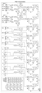
Let's move on to the electrical part of the active subwoofer. The general scheme and principle of operation of the device is represented by this scheme.

The device consists of four blocks assembled on separate printed circuit boards.
- Adder block (Summators),
- Filter unit (Subwoofer driver),
- Power amplifier block,
- Power supply (Power supply) and cooling unit (Heatsink fun).
First, the audio signal enters the Summators block, where the signals of the right and left channels are summed. Then it enters the filter unit (Subwoofer driver), where the subwoofer signal is formed, which includes a volume control, subsonic filter (low-pass filter), bass booster (volume increase at a certain frequency) and Crossover (low-pass filter). After formation, the signal enters the power amplifier unit (Power amplifier), and then to the loudspeaker.
We will discuss these blocks separately.
2.1. Block of adders (Summators)
2.1.1.Scheme
First, consider the adder circuit shown in the figure below.
The audio signal from external devices (computer, CD player……..) goes to the adder block, which has 6 stereo inputs. 5 of them are ordinary line inputs, differing from each other only in the type of connector. And the sixth is a high-voltage input, to which you can connect the speaker output (for example, a music center or car radio that do not have a line output). Each input has a separate op-amp combiner that shifts the right and left channel signals, which prevents the sound signal from one external device from being transmitted to another, while making it possible to connect several external devices to the subwoofer at the same time. And there are also outputs (5 outputs, the 6th one simply did not fit on the board, and therefore did not install), which make it possible to apply the same signal that enters the subwoofer to the input of a broadband stereo system. This is very convenient when the sound source has only one output.


2.1.2.Components
TL074 (5 pcs.) were used as operational amplifiers. Resistors are rated for 0.25W or higher (resistance ratings are shown in the diagram). All electrolytic capacitors have a voltage rating of 25 volts or higher (capacitance ratings are shown in the diagram). As non-polar capacitors, you can use ceramic or film capacitors (film is better), but if you really want to, you can put special audio capacitors (capacitors designed for use in high-quality audio systems). Chokes in the power supply circuit of operational amplifiers are designed to suppress the “noise” coming from the power supply. Coils L1-L4 contain 20 turns wound with copper wire with a diameter of 0.7mm, on the core of a gel pen (3mm). RCA, 3.5mm audio jack, 6.35mm audio jack, XLR, WP-8 connectors are also used.

2.1.3.Printed circuit board


The printed circuit board is made according to . After soldering the parts, the printed circuit board should be coated to avoid oxidation of the copper.
2.1.4. Photo of the finished adder block


The adder unit is powered by a bipolar ±12V power supply. The input impedance is 33kΩ.
2.2 Filter block (Subwoofer driver)
2.2.1.Scheme
Consider the subwoofer driver circuit shown in the figure below.

The summed signal from the adder block enters the filter block, which consists of the following parts:
- Volume control (volume regulator),
- Infra low pass filter (subsonic filter),
- Bass amplifier of a certain frequency (bass booster),
- Low pass filter (crossover).
Volume control takes place at two levels. The first is when the signal enters the filter block, which reduces the level of the own “noise” of the adder block, the second when the signal leaves the filter block, which reduces the level of the own “noise” of the filter block. The volume is adjusted using a variable resistor VR3. After the first level of volume control, the signal enters the so-called “bass booster”, which is a device that increases the amplitude of signals of a certain frequency. That is, if the bass booster tuning frequency is inserted, for example, at 44Hz, and the gain level is at 14dB, then the frequency response looks like this ( Row1).

Row2- tuning frequency=44Hz, gain level=9dB,
Row3- tuning frequency=44Hz, gain level=2dB,
Row4- tuning frequency=33Hz, gain level=3dB,
Row5- tuning frequency=61Hz, gain level=6dB.
The tuning frequency of the bass booster is inserted using a variable resistor VR5 (within 25 ... 125Hz), and the gain level with a resistor VR4 (within 0 ... + 14dB). After the bass booster, the signal enters the subsonic filter, which is a filter that cuts off unwanted, ultra-low signals that are no longer audible to humans, but can severely overload the amplifier, thereby reducing the actual output power of the system. The cutoff frequency of the filter is adjusted using a variable resistor VR2 within 10 ... 80 Hz. If, for example, the cutoff frequency is inserted at 25Hz, then the frequency response has the following form.
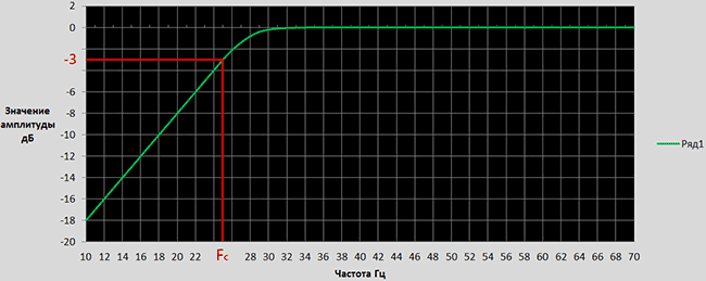
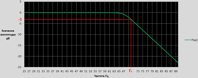
After the infra-low pass filter, the signal enters the low-pass filter (crossover), which cuts off the upper, unnecessary for the subwoofer (mid + high) frequencies. The cutoff frequency is adjusted using a variable resistor VR1 within 30 ... 250 Hz. The slope of the attenuation is 12 dB / octave. The frequency response has this form (at a cutoff frequency of 70 Hz).
2.2.2.Components
TL074 (2pcs), TL072 (1pc) and NE5532 (1pc) were used as operational amplifiers. Resistors are rated for 0.25W or higher (resistance ratings are shown in the diagram). All electrolytic capacitors have a voltage rating of 25 volts or higher (capacitance ratings are shown in the diagram). As non-polar capacitors, ceramic or film capacitors (preferably film ones) can be used. Chokes in the power supply circuit of operational amplifiers are designed to suppress the “noise” coming from the power supply. Three double (50kOhm-2pcs, 20kOhm-1pcs) and two quad variable (50kOhm-6pcs) resistors are also used. Two dual resistors can be used as quad variable resistors.
2.2.3.Printed circuit board

PCB files in *.lay and *.pdf format can be downloaded at the end of the article.
2.2.4. Photo of the finished filter unit


The filter unit is powered by a bipolar ±12V power supply.
2.3. Block power amplifier (Power amplifier).
2.3.1.Scheme
An Anthony Holton amplifier with field-effect transistors in the output stage is used as a power amplifier. There are a lot of articles describing the principle of operation, assembly and tuning of the amplifier on the Internet. Therefore, I will limit myself to embedding the schematic and my version of the PCB.

2.3.2.Printed circuit board


PCB files in *.lay and *.pdf format can be downloaded at the end of the article. The power amplifier unit is powered by a bipolar power supply with a voltage of ± 50 ... 63V. The output power of the amplifier depends on the supply voltage and the number of pairs of field-effect transistors (IRFP240 + IRFP9240) in the output stage.
2.4. Power supply and cooling unit (Power supply)
2.4.1.Scheme

2.4.2.Components
As a power transformer, you can use both a ready-made and a home-made transformer with a power of approximately 200W. The voltages of the secondary windings are shown in the diagram.


The diode bridge Br2 is designed for a current of 25A. Capacitors C1 ... C12, C29 ... C31 must have a rated voltage of 25V. Capacitors C13…C28 must have a nominal voltage of 63V (when the supply voltage is below 60V), or 100V (when the supply voltage is above 60V). As non-polar capacitors, it is better to use film capacitors. All resistors are rated at 0.25W. The R5 thermistor is smeared with thermal paste and attached to the amplifier heatsink. The operating voltage of the fan is 12V.
2.4.3.Printed circuit board

PCB files in *.lay and *.pdf format can be downloaded at the end of the article.
3. The final stage of subwoofer assembly


List of radio elements
| Designation | Type | Denomination | Quantity | Note | Shop | My notepad | |
|---|---|---|---|---|---|---|---|
| U1-U5 | Operational amplifier | TL074 | 5 | To notepad | |||
| C1-C4, C15, C16, C25-C27, C29, C39-C42 | 10uF | 14 | To notepad | ||||
| C5-C10, C23, C24, C28, C30, C35-C38 | Capacitor | 33 pF | 14 | To notepad | |||
| C11-C14, C19-C22, C31-C34 | Capacitor | 0.1uF | 12 | To notepad | |||
| C17, C18 | electrolytic capacitor | 470uF | 2 | To notepad | |||
| R1, R2 | Resistor | 390 ohm | 2 | To notepad | |||
| R3, R12 | Resistor | 15 kOhm | 2 | To notepad | |||
| R4, R16-R18 | Resistor | 20 kOhm | 4 | To notepad | |||
| R5, R13-R15 | Resistor | 13 kOhm | 4 | To notepad | |||
| R6, R10, R23, R24, R31, R33, R40, R41, R46, R47 | Resistor | 68 kOhm | 10 | To notepad | |||
| R7, R11, R21, R22, R32, R34, R37, R38, R45, R48 | Resistor | 22 kOhm | 10 | To notepad | |||
| R8, R9, R25, R26, R29, R30, R39, R42, R49, R50 | Resistor | 10 kOhm | 10 | To notepad | |||
| R19, R20, R27, R28, R35, R36, R43, R44 | Resistor | 22 ohm | 8 | To notepad | |||
| L1-L4 | Inductor | 20x3mm | 4 | 20 turns, wire 0.7mm, rim 3mm | To notepad | ||
| L5-L13 | Inductor | 100 mH | 10 | To notepad | |||
| Filter block | |||||||
| U1 | Operational amplifier | TL072 | 1 | To notepad | |||
| U2, U4 | Operational amplifier | TL074 | 2 | To notepad | |||
| U3 | Operational amplifier | NE5532 | 1 | To notepad | |||
| C1-C5, C7-C10, C15-C17, C20, C23 | Capacitor | 0.1uF | 14 | To notepad | |||
| C6 | Capacitor | 15 nF | 1 | To notepad | |||
| C11-C14 | Capacitor | 0.33uF | 4 | To notepad | |||
| C21, C22 | Capacitor | 82 nF | 2 | To notepad | |||
| VR1-VR3, VR5 | Variable resistor | 50 kOhm | 4 | To notepad | |||
| VR4 | Variable resistor | 20 kOhm | 1 | To notepad | |||
| R1, R3, R4, R6 | Resistor | 6.8 kOhm | 4 | To notepad | |||
| R2, R10, R11, R13, R14 | Resistor | 4.7 kOhm | 5 | To notepad | |||
| R5, R8 | Resistor | 10 kOhm | 2 | To notepad | |||
| R7, R9 | Resistor | 18 kOhm | 2 | To notepad | |||
| R12, R15-R17, R20, R22, R26, R27 | Resistor | 2 kOhm | 8 | To notepad | |||
| R18, R25 | Resistor | 3.6 kOhm | 2 | To notepad | |||
| R19, R21 | Resistor | 1.5 kOhm | 2 | To notepad | |||
| R23, R24, R30, R31, R33 | Resistor | 20 kOhm | 5 | To notepad | |||
| R28 | Resistor | 13 kOhm | 1 | To notepad | |||
| R29 | Resistor | 36 kOhm | 1 | To notepad | |||
| R32 | Resistor | 75 kOhm | 1 | To notepad | |||
| R34, R35 | Resistor | 15 kOhm | 2 | To notepad | |||
| L1-L8 | Inductor | 100 mH | 1 | To notepad | |||
| Power amplifier block | |||||||
| T1-T4 | bipolar transistor | 2N5551 | 4 | To notepad | |||
| T5, T9, T11, T12 | bipolar transistor | MJE340 | 4 | To notepad | |||
| T7, T8, T10 | bipolar transistor | MJE350 | 3 | To notepad | |||
| T13, T15, T17 | MOSFET transistor | IRFP240 | 3 | To notepad | |||
| T14, T16, T18 | MOSFET transistor | IRFP9240 | 3 | To notepad | |||
| D1, D2, D5, D7 | rectifier diode | 1N4148 | 4 | To notepad | |||
| D3, D4, D6 | zener diode | 1N4742 | 3 | To notepad | |||
| D8, D9 | rectifier diode | 1N4007 | 2 | ||||
SUBWOOFER OWN HANDS
Sooner or later, many people realize that there is never a lot of bass, and no matter how much they look for more powerful speakers, they still want more bass. The only way out is to use a subwoofer. You can buy a good subwoofer, but not everyone can find the extra $200 - $300. So let's make a subwoofer with our own hands!
First, we will solve the issue with power: a good transformer, 150 watts, having the necessary bipolar voltage and current does not lie on the road, but I really don’t want to wind it myself. And it is not necessary. We buy an electronic transformer for a standard voltage of 12 V and a power of 100 - 150 watts and connect a K40x30x20 ferrite ring with a primary winding of 13 turns of PEL 1.2 to its output; two secondary of 28 turns of the same wire have a bipolar voltage of 25 V.
Scheme do-it-yourself subwooferconsists of an active filter on TL082 (TL062) and the amplifier itself, assembled according to a standard push-pull circuit. To improve the sound quality (and who said that the bass is not critical to the distortion factor?), There is a pair of field-effect transistors at the output. In more detail about the LPF - calculation, diagram and drawings of printed circuit boards. One of the excellent filter circuit options for a subwoofer with a phase shifter is in the figure.

Powered by subwoofer or from the aboveelectronic transformer, or from a conventional one on a transformer, with two windings of 20 - 30 V each for a current of 3 A.

It should be taken into account thatelectronic transformers do not work at low load currents, so thisDIY subwooferworks in class A, which, as you understand, is also very well reflected in the sound quality. The current consumption of each arm must be at least 0.6 A. It is set with a trimming resistor of 1 k.
Alternatively, you can use the TDA7294 chip, included in the diagram below, as an UMZCH.

speaker for do-it-yourself subwooferwe take any low-frequency, the more powerful - this sub produces more than 100 watts of pure sine. Power supply +-30 V, with a maximum current consumption in peaks, up to 4 A. The measured harmonic distortion is less than 0.1%.

For body do-it-yourself subwooferwe use an old Soviet wooden TV, you can use a tube or 3USCT.

From above in the center we make a cut, and we get two sides with halves of the upper part. That is, two letters G. We turn one of them over - the frame is ready, and the bottom will be used as the back wall. Caulk the joints with sealant and do not forget to make a phase inverter hole with a diameter of 8 mm in front.More information about the calculation and manufacture of the hull can be found on other resources. And here read practical detailed assembly example


