Which oil to fill in the tractor t 40. Maintenance of oil centrifuge
T-40 - Tractor on a wheelchair designed for operation in the agricultural and road sphere. Traction class 0.9. Manufacturer - Lipetsk Tractor Plant. Release period - 1961-1995. Now the tractor is removed from production, but are still in operation. Causes of long service life - construction durability, versatility and optimal conditions for repair: All spare parts are available.
Characteristics T-40
Purpose: ➤ Pachote; ➤ processing of field crops; ➤ Cathes; ➤ Cleaning hay, storage; ➤ Snow clearance; ➤ Bulldozer and transport work. Operational features: ➤ High Patency; ➤ Good maneuverability (thanks to a reversible transmission, the entire functionality of the machine is available in the back); ➤ Adjustable track and lumen; ➤ Two power take-off shaft; ➤ Various options for installing wheels depending on the specific purpose.Specifications
➤ Power: 37 and 50 hp ➤ Speed \u200b\u200brange: 1.6 - 27 km per hour. ➤ Constructive weight: 2.3-2.6 tons.
Number of gears: 7. Traction effort: 1st transmission - 1100; 2nd - 990; 3rd - 800; 4th - 640. Dimensions of the basic model: Length - 366 cm; Width - no more than 210; Height - no more than 253 cm.
T-40 tractor motor
Production - Vladimir Tractor Plant. The basic version of the machine (T-40 is equipped) the engine D-37 (performance - 37 hp, 27 kW). Its analogue T-40m has a D-144 engine (50 hp, 37 kW). ➤ Type: Diesel ➤ Number of cylinders: 4 ➤ Volume: 4.15 l ➤ Cylinder diameter: 10.5 cm ➤ Piston stroke: 12.0 cm ➤ Frequency: 1500 (37) and 1800 (50) OB. per minute ➤ Torque: 192 and 205 ➤ Specific consumption when expl. Power: no more than 246/248 grams per kilowatt-hour ➤ Run: electric starter, gasoline PD8 ➤ Cooling type: Aerial As for fuel consumption, it all depends on the load on the engine, as well as what works the tractor performs. For example, the nominal norm is 7.2 liters per hour.Device
A motor is placed on the half frame, rigidly connected to the gearbox, there is a rear axle. The half-frame is connected to a diesel crankcase with elastic gaskets. It is a carrier part of the design and performs the function of the shock absorber when driving on uneven terrain. The conical gearbox is placed behind the clutch of the clutch, gearboxes are located transversely. Dual coupling: Home combined with power take-off coupling. Behind the drive and the control unit of both shafts (rear and lateral). Shafts can work and synchronously, and independently. The steering column of the tractor with the help of a cardan shaft on the hydroper wheel of the steering wheel from the steering wheel through the sushka transmits movement and thereby ensures the rotation of the guides in the desired direction. The T-40 generator is made by the type of three-phase contactless electromascy. It has one-sided electromagnetic excitation, voltage regulators and built-in rectifiers.Transmission
➤ Mechanical, reversible. ➤ Gearbox - four-way, 8 speeds, reverse, blocker. The location of the shafts is transverse; ➤ Differential - closed, two-calves with forced blocking; ➤ gear shift; ➤ Main transmission: gears straight cylindrical; ➤ Central: gears spiral conical.Installation of the track is allowed (if the speed of the tractor is much lower than the speed of its movement).
T-40 tractor hydraulic system
The T-40 tractor hydraulics has the following characteristics: ➤ Hydraulic heater hydraulic. ➤ Hydro-distributor four-position three-rod. Accommodation on the rear wall of the battery pack. ➤ Main cylinder 9 cm. Piston stroke to 20 cm, hydromechanical adjustment. ➤ Remote cylinder 5.5-7.5 cm. ➤ Oil pump gear. Placement in front of diesel. ➤ Hydrobac. Posted on the bracket of the hydraulicel. ➤ The jacket mechanism is the rear of the transmission block. ➤ Connection of agricultural customs - three-point. ➤ Connecting hoses.
T-40 Tractor Hydraulic Scheme
1 -Gidobac; 2 - pump; 3 - flow division valve; 4 - spool; 5 - springs of the spool; 6 - filter; 7 - power steering; 8 - hydraulic distributor; 9 - main hydraulic cylinder; 10 - The remote hydraulic cylinders of the T-40 tractor hydraulic cylinders consists of a gear pump 2 , Valve 3 Flow division, hydraulic 1 with filter, hydraulic 7 Steering, hydraulic distributor 8 , main and remote hydraulic cylinders, locking devices of discontinuous couplings, pipelines and hoses. Glue oil 1 Enters the gear pump 2 that injected it into the valve 3 Flow division. The valve divides the flow of oil into two parts: one enters the hydrodistrator 8 hydraulic system, other - in the power steering 7 . The hydrodistrator directs the flow of oil or in the hydraulic tubing on the drain oil, or to the hydraulic cylinder 9 Or through side or rear conclusions directly to the hydraulic nature of the agricultural machine.Wheels
In large rear wheels, a rigid suspension, in the front (with a small diameter) - spring. The protector on the rubber - the Christmas tree. Wheel installation options: ➤ Rear with less width; ➤ double; ➤ "inside out", asymmetric disk plane (with a large slope steepness).Power point
The tractor engine has a relatively simple design. The power plant is located on a half-frame that is rigidly connected to the crankcase. The component unit has four-stroke diesel execution. The engine is equipped with four cylinders. Depending on the modification of T-40, the engine D-37 or D-144 can be completed, the nominal power potential of which is 37 and 50 hp. respectively. Starting the installation is carried out by means of an electric starter. Such an engine with an air cooling option does not have a Carter block. His cylinders have a removable execution. The presence of radiator edges contributes to the improvement of heat sink. Engine cylinders are located in a row. The thermal loads on the oil of such a motor are slightly higher than in the automotive variation of the device, so it becomes necessary for its high-quality cooling. It should be noted that with such a task, the designers coped not very well.The presence of special oil type radiators makes it possible to additionally cool the power work, thanks to which you can talk about the efficiency of the engine in any conditions.
Advantages and disadvantages of T-40 tractor
Pros: High passability on any soil. Easy maneuvering at any speed. The entire functionality of the tractor is available in the back. Ease of control. Universality: The possibility of configuration by mounted equipment for other types of machines (T-25, "Belarus"). Lack of spare parts and maintenance problems. Reliability, durability. The steering of the tractor is equipped with a power steering.
Modifications
With engine d-37
The basic model has a rear-wheel drive. Its modifications are made with a full drive: ➤ T-40A - the presence of anterior bridge. The front actuator connects automatically in accordance with the conditions of movement; ➤ T-40Un - the tractor is adapted to work on steep slope, height and road lumen is less than the basic version; ➤ T-50A - industrial modification, adapted for a single-line loader.With engine d-144
T-40m rear-wheel drive, modifications - full: ➤ T-40am - the difference from the T-40M - the front axle with the drive; ➤ T-40Anm - powerful analogue T-40An: reduced ground clearance to work on steep slope (up to 20 degrees), less height, greater stability; ➤ T-40AP - industrial model, adapted to work with road machinery. The gas distribution mechanism in the T-40 tractor engine from time to time needs to be checked and the most accurate adjustment of the valves, which is usually not performed in the repair, and in the working manner the machine operator itself. According to the technical rules, such adjustment should take place every 480 hours of the tractor. Principle of operation The gas distribution mechanism works as follows. The gear of the crankshaft across the gear of the camshaft and the intermediate gear leads to rotation the camshaft, which rotates, raises his fists pushers and through the rockers and the rods opens the graduation and intake valves. With further rotation of the camshaft, the cam ledge moves away from the pusher and under the influence of the springs the valve closes. The rod, the pusher and the rocker are returned to the initial position. Next, the cycle is repeated again in accordance with the phases of gas distribution. In order for the gas distribution mechanism to function synchronously with the fuel supply system, the camshaft gears - fuel pump and intermediate, must be installed in accordance with the labels applied to the gears.T-40 valve adjustment

How to adjust the T-40 valve
Before starting the adjustment of the gaps, remove the wedge of the back cardan and moving the shaft together with the wheel on itself, free the cardan and take it to the side. To adjust the gap, loosen the lock nut of the adjusting screw at the rocker and, unscrew or spinning the screw, install the desired gap using the dipstick, after that tighten the lock nut and measure the clearance again, turning the pusher bar. The valve must be adjusted only on a cold engine. The order of adjustment of the valves corresponds to the order of engine operation - 1-3-4-2. With the help of the tag V.M.T. And the pointer on the fan drive pulley, install the first cylinder piston to the end position of the compression tact, while close the exhaust and intake valves, and then turn the crankshaft to adjust the valves of the following cylinders with the key on? Turnover clockwise. With moderate operation of the engine, the valves remain tightness for a long time. To prevent the clips of the valves on the pump and the fallout of crackers - do not break the pairs of crackers when dismantling the valve mechanism. When replacing the gear of the distribution, enter them into engagement according to the marks appropriately.T-40 tractor decompressor
The decompressor is necessary to facilitate the start of the cold engine, as well as for emergency stop of the diesel. The mechanism consists of four levers and rails, hinged with a rail. The levers are rigidly associated with rollers, the filled ends of which are included in the pushing of the inlet valves. When moving the rail, levers are rotated with rollers, raising pushers, and those in the rods and rods open intake valves.
How to start the T-40 with a start
Lubricate the crank-connecting mehnism (CSM) start. To do this, it is necessary to open the air damper of the carburetor and scroll through the crankshaft starter starter for 2-3 seconds. Next, not including the starter, turn on the ignition and open the damper, moving the control lever forward. When starting the engine, the starter time does not exceed 15 seconds. If the starting unit did not start - repeat the operation after a minute. If after 3-4 attempts at the start and did not start, make sure that the PPC lever is in a neutral position; Check the power and ignition system. After the starting unit began to release the starter switching lever. The starting unit must be warm up for 2-3 minutes, giving it to work first on minimal revs, and then bring to the rated frequency of rotation. The rapid rotation frequency is changed by the position of the air damper using the thrust. After the starting unit warmed up - stop it and enter the lead gear gear with the crown of the T-40 engine flywheel by pressing the pedal foot. Turn off the gearbox. Run the start and set the maximum speed; Turn on the incandescent chamber of the switch. After the control element is glowing, smoothly turn on the clutch clutch clutch. Scrolling the engine within 3-5 seconds, enable compression. As soon as the first flashes appear when the engine starts to gain momentum, turn on the starting gear, removing the foot from the pedal and muffle the starting unit with the ignition off button. Close the fuel tank cranch for the starting unit. The time of operation of the start at full revolutions should not exceed 15 minutes. Time exceeding can cause its overheating and failure. It is forbidden to start a starting unit without prior disconnection from the engine. Also, the T-40 tractor can be started using Schoregorea (manual starter). To do this, it must be fixed on the flywheel of the start and turn on the decompressor. The hot engine is hardened without switching on the decompressor. Immediately after the engine is headed, turn on the hydraulic pump. Check the readings of the control devices. The engine warms up within 2-3 minutes on the nominal turnover of the crankshaft.1. Before replacing the lubricant, let the T40 tractor engine, bring the oil temperature in the crankcase pallet to 50 ° (no less) and stop it. Immediately after stopping the engine, drain the oil from the pallet.
2. Clean the magnet, flange, oil pump receiver Metal particles and rinse the magnet and the net of the receiver in diesel fuel; Put the flange with the receiver in the place.
3. Clean and rinse the rotor, body and cap centrifuge.
4. Fill into the pallet Carter Fresh oil recommended by the plant.
In order to avoid looting of the liners of the T40 tractor crankshaft bearings, even the short-term operation of the engine is strictly prohibited with a diesel fuel in its pallet.
Maintenance of oil centrifuge
To clean the oil on the engine installed a full-flow reactive centrifuge (Fig. 17).
Maintenance of oil centrifuge T40 tractor consists in cleaning and washing with clean diesel fuel every 120 hours of operation.
Fig. 17. Oil filter (centrifuge)
1 - Lower sleeve; 2 - nozzle; 3 - body; 4, 17, 19 - sealing gaskets; 5 - Cap; 6 - Rotor cover; 7 - Nut Rotor Cover; 8 - Stubborn Ring; 9 - nut; 10 - Rotor axis; 11 - the tube is brazed; 12 - oil-tapping tube with a filter grid; 13 - Tube reporting; 14 - Rotor base; 15 - plug; 16 - Oil radiator switch; 18 - bolt; 20 - threaded plug; 21 - Spring; 22 - radiator safety valve ball; 23 - centrifuge safety valve ball.
Valves 22 and 23 in 1971 will be canceled.
Disassembly and cleaning in the following sequence:
1. Unscrew the nuts of two cap fastening bolts and remove it.
2. Unscrew the nut 9 (Fig. 17) and remove it along with the thrust ring.
3. Carefully remove the 10 rotor from the axis.
4. Unscrew the nut 7 and remove the 5 rotor cover along with the sealing gasket.
5. Remove the sediment layer from the inner walls of the cover 6 and the bottom bottom of the base 14 and thoroughly rinse the rotor parts in pure diesel fuel.
6. Clean the copper or brass wire with a diameter of 1.5-1.8 mm output openings 2.
Check out the cleanliness of the holes in the axis 10 and in the coupling tube 11, the mesh of the oil pump tubes 12, if necessary, clean.
Build the rotor and fix it on the axis in the reverse order.
To preserve the risky rotor balancing (tags), applied to the base and the rotor cover, must be combined when assembling.
Check the maintenance of the centrifuge on the hearing as follows: Immediately after stopping the engine, it must be heard for 30 seconds gradually falling rotor noise.
Consulting and Implemented Center for SEC. 1C. Print the engine with the oil radiator included in the lubrication system, the arrow on the centrifuge housing should indicate the letter "L" of the switch; When working with the turned off by the radiator - the letter "3".
From the factory, T40 tractors are shipped with an inclusive oil radiator.
We rent a place to install payment terminals At the Moscow and Moscow Region Stations in the High Rental Rates on the site ARENDAMEST.RU
Lubrication system of diesel engine D144 T-40 tractor (Fig. 4) - combined. The most loaded rubber surfaces are lubricated under pressure, the rest is splashing.
Under pressure, the oil goes to the conjugation of the following parts: indigenous and connecting rod bearings, camshaft bearings, an intermediate gear of the gas distribution mechanism, etc.
Fig. 4. Diesel engine lubrication system D-144 Tractor T-40
1 - oil filter (centrifuge); 2-shallular radiator; 3 - oil temperature pointer; 4 - oil pressure pointer; 5 - gear of the fuel pump drive; B - Switch "Winter - Summer"; 7 - intermediate gas distribution gears; 8 - oil pump; 9 - reduction
valve
The remaining parts of the motor system D-144 T40 tractor are smeared: the oil is squeezed out of gaps and special holes, flows into the oil crankcase and forms an oil fog.
Oil pump, reducing valve, oil filter (centrifuge), oil radiator are assigned to the lubricant system.
Diesel Lubrication System D144 Tractor T-40
Oil from the bottom of the crankcase through the oil pump of the pump 8 (see Fig. 4) is injected into a full-flow reactive-oil filter 1 (centrifuge), where it is cleared of mechanical impurities and precipitation.
From the filter, purified oil enters the oil radiator 2 (re-key of the radiator in the "Summer" position) or directly into the lubricant highway located in the block (the radiator switch in the Winter position).
On the channels in the partitions of the engine cylinder block D-144 T-40 tractor, the oil goes to the third root bearing, from where the drills in the cheeks and crankshaft crankshafts are to connecting rod and native bearings.
From the first indigenous bearing, the oil is supplied to lubricate the gears of gas distribution and the first cervication shaft. For the lubrication of the second and third neck of the camshaft, the oil comes from the third and fifth native crankshaft bearings. To the valve
The mechanism oil comes with a pulsating stream.
On the channels in the crankcase and the tube in the cover of the camshaft gear, through the hole in the front sheet, the oil enters the fuel pump mounting flange and the fuel pump drive gear sleeve.
When the compressor is installed on the diesel engine, the oil through the hole in the front sheet of the diesel engine and the hole in the compressor housing is entered for lubricating the compressor.
From the connecting rod neck of the crankshaft of the engine d-144 T-40 tractor to drill in the rod rod, the oil goes to cool the bottom of the piston and lubrication of the piston finger.
Self lubricates the pair of the valve rod - the valve sleeve. All other parts are lubricated with splashing and oil pairs (oil fog).
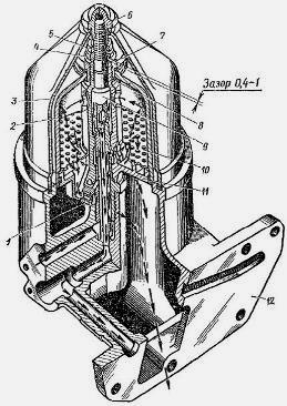
Fig.5. Oil filter (centrifuge) engine D-144 T40 tractor
1 - nozzle; 2 - Rotor cover; 3 - Cap; 4 - Stubborn washer; 5, 6, 7 -Gikes; 8 - locking Kolio; 9 - Rotor axis; 10 - reflector; 11 - Rotor base; 12 - housing
The oil pressure in the highway is controlled by a pressure pointer 4. The normal oil pressure during the heated diesel engine and the nominal rotation frequency should be within 0.15-0.4 MPa (1.5-4 kgf / cm2).
With oil pressure below 0.15 MPa (1.5 kgf / cm2), diesel should be stopped to detect and eliminate the causes causing a reduced oil pressure.
When working with a diesel engine with an oil radiator included in the lubricant system, the arrow, cast on the housing 12 (Fig. 5), the centrifuge should be indicated by the letter "L" of the switch when working with a disconnected radiator - the letter "3".
Principle of operation of the main mechanisms of the engine lubrication system D-144 T-40 tractor
The reducing valve (Fig. 6) is used to regulate and maintain constant pressure in the lubricant system. The valve consists of a housing, ball, gaskets, nuts, springs, adjusting plugs.
Oil from the pump through the tubes enters a reduction valve, which is adjusted to the pressure of 0.64-0.69 MPa (6.5-7 kgf / cm3). At a pressure of 0.69 MPa (7 kgf / cm2) and above oil, the oil presses on the ball 5, and through the pego on the spring 4. The spring is compressed, the ball departs, opening the hole through which part of the oil is merged into the crankcase.
To clean the oil on the diesel engine D-144 of the T-40 tractor, a jet oil filter (centrifuge) is installed (see Fig. 5). It passes through it all the oil entering the lubricant system of diesel engine, and a part of the oil supplied by the pump is merged during the operation of a diesel engine through a reduction valve into an oil crankcase.
The filter consists of a housing, the base of the rotor, reflector, the axis of the rotor, the locking rings, nuts, the stubborn washer, the cap, the rotor cover, nozzles. The oil comes from the pump passes through the channel in the body 12 centrifuges and the ring gap between the tube and the axis 9 of the rotor, through the holes in the axis and the base of the rotor, then through the reflector 10 to the rother cavity.
In the rotor cavity, the pressure reaches 0.64-0.69 MPa (6.5-7 kgf / cm2). Under this pressure, part of the oil, passing through the reflector, comes to the nozzles / (nozzles) and, leaving them at high speed, creates a reactive force that leads the rotor into rotation.
Particles (mechanical impurities) in oil are discarded to the walls of the rotor and settle on them. Purified oil through the tangential hole and on the central channel in the rotor axis enters the main line.
Conditions of the Lubricant System of the engine D-144 Tractor T-40
To ensure normal operation of the engine diesel engine D-144 T40 T40, the following rules must be followed:
Pour oil into a diesel carter only with clean dishes through a funnel with a frequent grid,
Do not allow diesel operation at the oil level in the oil curtain below the lower and above the top labels of the oil level pointer.

Fig. 6. Reducing valve of the engine lubrication system D-144 T-40 tractor
1 - nut; 2 - washer; 3 - adjusting plug; 4 - spring; In - valve ball; 6 - housing
Method of adjusting the oil pressure in the lubricant system of diesel engine D144 T-40 tractor
Using a reduction valve, you can increase or lower the oil pressure. To do this, bend the puck 2 (see Fig.6), unscrew the nut 1 and turning the screwdriver 3, squeeze or weaken the spring 4, pressing the ball 5.
When turning the traffic jam to the right, the pressure in the system rises, and when it turns to the left - decreases.
Upon reaching the desired pressure in the lubricant system in the range of 0.15-0.4 MPa (1.5-4 kgf / cm2) (according to the pressure pointer on the instrument panel), it should be wrapped the nut 1 and in-block it with a gasket 2.
________________________________________________________________________
Lubricant diesel system (Fig. 1) - combined.
The most loaded rubber surfaces are lubricated under pressure, the rest is splashing.
Under pressure, the oil goes to the conjugation of the following parts: indigenous and connecting rod bearings, camshaft bearings, an intermediate gear of the gas distribution mechanism, etc.
Fig. 1. Lubricant system:
1 - oil filter (centrifuge); 2 - oil radiator; 3 - oil temperature pointer; 4 - oil pressure pointer; 5 - gear of the fuel pump drive; 6 - Switch "Winter-Summer"; 7 - Intermediate gear of gas distribution; 8 - oil pump; 9 - reduction valve
The remaining parts are smeared with splashing, the oil is squeezed out of the gaps and special holes, flows into the oil crankcase and forms an oil fog.
Oil pump, reducing valve, oil filter (centrifuge), oil radiator are assigned to the lubricant system.
Scheme of the lubricant system of diesel. Oil from the bottom of the crankcase through the oil pump of the pump 8 (see Fig. 1) is injected into a full-flow reactive-oil filter 1 (centrifuge), where it is cleared of mechanical impurities and precipitation. From the filter, the purified oil enters the oil radiator 2 (the radiator switch in the "Summer" position) or directly into the lubricant highway located in the block (the radiator switch in the Winter position). On the channels in the partitions of the block, the oil goes to the third root bearing, from where in the drills in the cheeks and crankshaft crankshafts - to connecting rod and indigenous bearings. From the first indigenous bearing, the oil is supplied to lubricate the gears of gas distribution and the first cervication shaft. For the lubrication of the second and third neck of the camshaft, the oil comes from the third and fifth native crankshaft bearings. To the valve mechanism oil comes with a pulsating stream.
On the channels in the crankcase and the tube in the cover of the camshaft gear, through the hole in the front sheet, the oil enters the fuel pump mounting flange and the fuel pump drive gear sleeve.
When the compressor is installed on the diesel engine, the oil through the hole in the front sheet of the diesel engine and the hole in the compressor housing is entered for lubricating the compressor.
From the connecting rod neck of the crankshaft to drill in the rod rod, the oil goes to cool the bottom of the piston and lubrication of the piston finger.
Self lubricates the pair of the valve rod - the valve sleeve. All other parts are lubricated with splashing and oil pairs (oil fog).
The oil pressure in the highway is controlled by the pressure pointer 4. The normal oil pressure during the heated diesel engine and the rated frequency of rotation should be in the range of 0.15-0.4 MPa (1.5-4 kgf / cm²). With an oil pressure below 0.15 MPa (1.5 kgf / cm²), diesel should be stopped to identify and eliminate the causes causing low oil pressure. When working with a diesel engine with an oil radiator included in the lubricant system, the arrow, cast on the housing 12 (Fig. 2), should indicate the letter "L" of the switch when working with a disconnected radiator - the letter "3".
Principle of operation of the main mechanisms. The reducing valve (Fig. 3) serves to regulate and maintain constant pressure in the lubricant system. The valve consists of a housing, ball, gaskets, nuts, springs, adjusting plugs.
Oil from the pump through the tubes enters the reduction valve, which is adjusted for pressure 0.64-0.69 MPa (6.5-7 kgf / cm²). At a pressure of 0.69 MPa (7 kgf / cm²) and above the oil presses on the ball 5, and through it on the spring 4. Spring is compressed, the ball departs, opening the hole through which part of the oil is drained into the crankcase.
For cleaning oil on a diesel engine, a jet oil filter (centrifuge) is installed (see Fig. 2).  Fig. 2. Oil filter (centrifuge):
1 - nozzle; 2 - Rotor cover; 3 - Cap; 4 - Stubborn washer; 5, 6, 7 - nuts; 8 - stop ring; 9 - Rotor axis; 10 - reflector; 11 - Rotor base; 12 - housing
It passes through it all the oil entering the lubricant system of diesel engine, and a part of the oil supplied by the pump is merged during the operation of a diesel engine through a reduction valve into an oil crankcase. The filter consists of a housing, the base of the rotor, the reflector, the axis of the rotor, the locking rings, nuts, the stubborn washer, the cap, the rotor cover, nozzle, oil coming from the pump, passes through the channel in the body 12 centrifuges and the ring gap between the tube and the 9 rotor axis 9 , through the holes in the axis and the basis of the rotor, then through the reflector 10 to the cavity of the rotor. In the robe cavity, the pressure reaches 0.64 - 0.69 MPa (6.5-7 kgf / cm²). Under this pressure, part of the oil, passing again through the reflector, comes to nozzles 1 (nozzles) and, leaving them at high speed, creates a reactive force that leads the rotor into rotation. Particles (mechanical impurities) in oil are discarded to the walls of the rotor and settle on them. Purified oil through the tangential hole and on the central channel in the rotor axis enters the main line.
Conditions of the lubricant system.
- To ensure normal operation of the diesel, the following rules must be followed:
- pour oil into a diesel carter only with clean dishes through a funnel with a frequent grid.
- apply oil recommended by the plant. The use of autolas or other oils is unacceptable.
- do not allow diesel operation at the oil level in the oil curtain below the lower and above the top labels of the oil level pointer.
 Fig. 3. Reduction valve:
1 - nut; 2 - washer; 3 - adjusting plug; 4 - spring; 5 - valve ball; 6 - housing
Method for regulating oil pressure in lubricant system. Using a reduction valve, you can increase or lower the oil pressure. To do this, you need to bend the puck 2 (see Fig. 3), unscrew the nut 1 and turning the screwdriver 3% compress or weaken the spring 4, pressing the ball 5. When you turn the cork to the right, the pressure in the system rises, and when turning to the left - decreases. Upon reaching the desired pressure in the lubricant system within 0.15-0.4 MPa (1.5-4 kgf / cm²) (according to the pressure pointer on the instrument panel), the nut 1 should be wrapped and correcting it with a gasket 2. [T-40M tractors , T-40am, T-40NM. Technical description and instruction manual. 1989]
- Articles
In 1961, the Lipetsky Tractor Plant mastered the production of the tractor on a wheeling under the designation T-40.
A successful T-40 design, the good technical parameters of this universal-missing tractor helped gain popularity, which is confirmed by finding the conveyor until 1995. The advantages and advantages of the model of the agriculture range are counted:
- front arrangement;
- successful transmission and gearbox on T-40;
- efficiency of operation;
- reliability;
- maintainability.
These advantages of T-40 helped to develop modifications in demand in the fields of industry and in other industries. Among the main:
- 40am - all-wheel drive version;
- 41an - an option with reduced clearance for agricultural development on land slopes;
- 50a - Loader with a bucket;
- - tractor tractor;
- 40Ap - Modification for use in the housing and communal sphere.
Technical parameters T-40
 Multifunctionality in use and as a result, the T-40 popularity was provided by the technical characteristics, while the speed parameters coincide with:
- Class - 0.9.
- Load capacity - 0.85 tons.
- Drive - front (4x2).
- Engine - D-144:
- Type - diesel.
- The number of cylinders is 4.
- The volume of cylinders is 4.20 liters.
- Cooling - air.
- Power - 50.50 l. from.
- Dimensions:
- Length - 3.66 m.
- Height - 2.38 m.
- Width - 1.63 m.
- Wheel base - 2.15 m.
- Transmission:
- Mechanical.
- Switching diagram - 8 front and rear gear.
- Clutch is a friction one-piece coupling.
- The speed is the highest (smallest):
- front turn - 26.72 (1.63) km / h.
- reverse - 5.35 (1.96) km / h.
- General:
- Weight - 2.37 tons.
- The volume of tanks is 74.0 liters.
- Fuel consumption - 185 g / kW * h.
- Clearance - 0.65 m.
CPP device
 In the design of the T-40 tractor to change the direction of movement, the speed selection and operations, the gear change box is intended. The design of the box is represented by the following elements:
- by weight;
- reverse mechanism with conical transmission;
- locking device;
- special shafts, gears with switching mechanism;
- the main transmission with the device for blocking the differential.
- Podoomyshtel. The device is intended, instead of a dispensing box, form for T-40 an additional number of reduced speeds, as well as to increase the number of aggregative equipment when performing various works. The design of the movement is enlarged represents a gear transmission with external and internal engagement, which, when interacting with each other, form a reduced gear ratio (2.75), which is transmitted to the slave T-40 shaft.
- Reverse. The mechanism of reverse with a special transmission is designed to obtain an additional number of speeds in the box for movement by reverse. The design represents the gearbox, the principle of which is to change the gear gears in a conical transmission, at which the direction and speed of the driven shaft movement occurs.
- Special shafts and gears, switching mechanism. Designed to obtain the speed of movement or change direction. The box distinguishes primary and leading shafts, as well as gears gears. The necessary gear is obtained by the method of moving a given movable gear for its engagement with a fixed, located on another shaft. The switching mechanism is constructed using special switching shafts on which the mounted fork. Shafts move using the switch lever, while the plugs shifted moving gears.
- Transmission blocking device. The device is intended to eliminate the incomplete gear gear in the box, as well as spontaneous disconnection. The main element is a special shaft for blocking and clamps. When the required transmission is turned on in parallel, the blocking shaft is moving to the necessary gear and, with the coincidence of the teeth, the locks are fixed.
- Main Transmission with Differential Lock Device. It is used to broadcast the drive torque wheels from the engine, consists of two strap gears. The differential lock device is intended to obtain the same speed of rotation of the right and left tractor wheel.
Service
 For reliable durable work and reducing the number of repairs of the T-40 tractor, the T-40 tractor must be carried out, regulated by the manufacturer.
An important operation is to check the quality, level, as well as the lubricant life in the case of the box.
High-quality transmission oil will protect gears and trees from premature wear, corrosion.
It is necessary to use lubricant with a given temperature regime by period of operation (summer, winter, all-season).
The frequency of oil level verification is performed by each 240 operation hours. Check the level with a control plug, which is located on the CP body.
In the case of a reduced level, oil is poured to the norm through the control opening. It is strictly not recommended to fill the transmission fluid above the level of the check mark, as this will lead to the creation of an increased density of the oil film on the engagement teeth, which causes deformation.
When changing the transmission fluid, every 960 hours of work is required to wash the elements, box nodes. To do this, the oil drops from the hot engine, which allows you to clean the box from deposits.
Also in the PPP T-40, the gear gear gear is not adjustable until fully losing performance.
The implementation of such simple operations will allow efficiently servicing the transmission, increase the period of operation of the multifunctional T-40.


