Design Description
The power system consists of a fuel tank with a fuel pointer sensor and a fuel reserve, fuel pipelines, fuel pump, air filter and carburetor.
Engine power supply parts:
1 - carburetor; 2 - air intake of warm air; 3 - cold air intake; 4 - air filter housing cover; 5 - filter element; 6 - air filter housing; 7 is the level indicator sensor and fuel reserve; 8 - bay neck; 9 - ventilating hose; 10 - fuel tank; 11 - fuel line; 12 - fuel hose; 13 - fuel filter; 14 - Fuel PumpBy car with a body sedan installed fuel tank A volume of 39 liters, which is welded from two halves, postponed from leafled steel, is painted with black enamel outside. The tank is located in the trunk on the right side along the movement of the car and is attached to the body of a clamp, pulled by a bolt. The fuel neck of the tank is displayed in a niche on the right rear wing and closed with a threaded plug. For ventilation, the fuel tank has a hose derived in a niche of the filler neck. From above on the tank through the sealing gasket, a level indicator sensor and fuel reserve is installed. From the sensor on the instrument panel, data is displayed on the fuel residue in the tank. When the fuel remains 4.0-6.5 l on the instrument panel, the control lamp lights up. By car with a body, a 40-liter fuel tank was installed under the baggage branch, and fastened to the bottom of the body to four bolts. The fuel neck of the tank is bred in a niche on the left back of the wing.
The fuel lines are made of steel galvanized tubes and are fixed from below on the bottom of the body holders. Details of the fuel system are interconnected by rubber hoses fixed by tight clamps.
Fuel pump -Diaphragmented type, with mechanical drive and manual swing lever. The pump is located on the left side of the cylinder block and is fixed through the thermal insulation spacer and gaskets on two heels with nuts. The pump drive is carried out through the pusher from the eccentric on the actuator shaft of the auxiliary units or from the manual swing lever. The pump capacity is at least 60 l / h at a swing frequency of 2000 cycles per minute. The pressure generated by the pump is in the range of 0.2-0.3 kgf / cm². The pump consists of a lower case with drive levers, an upper case with inlet and injection valves, a diaphragm node and a cover. The diaphragm node has two top workers and one lower (safety) diaphragms installed on the rod. Internal and external remote gaskets are installed between the working and safety gasket. In order to prevent fuel from entering into the engine crankcase in case of damage to the working diaphragms of the fuel pump in the outer gasket, a hole for draining fuel is performed.
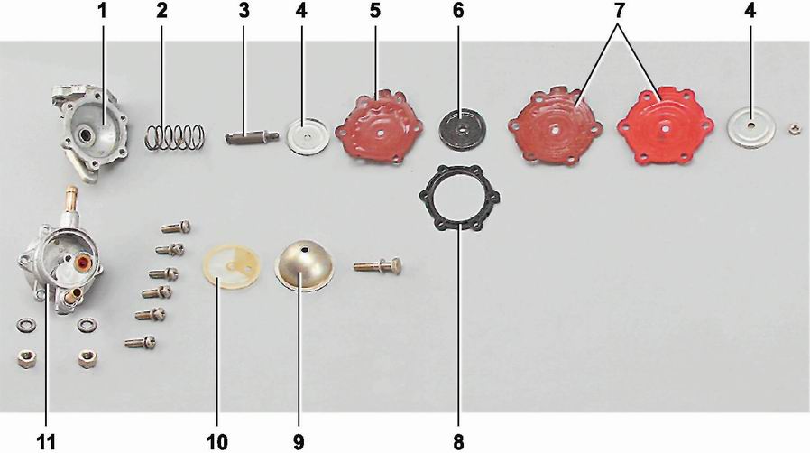
Fuel pump details:
1 - lower case; 2 - return spring; 3 - rod; 4 - a plate of a diaphragm node; 5 - safety diaphragm; 6 - internal remote gasket; 7 - working diaphragms; 8 - external remote gasket; 9 - pump cover; 10 - Mesh filter; 11 - Upper CaseAir filter is dry, with a replaceable filtering element that can be cleaned by air carburetor. The filter housing is mounted on the carburetor cover through a rubber gasket with remote sleeves on four studs and is attached to self-locking nuts. From above, the filter housing is closed with a rubber sealing gasket. The air into the air filter body enters the air intake of cold air or through the nozzle connected by the corrugated hose with the air intake of warm air, from the exhaust manifold zone. Air intake through the air intake or nozzle overlaps the partition BUTfixed on the lid.
Depending on the season, the lid is rearranged into the required position (in the summer the receipt of warm air, in winter - cold).
The air filter housing is connected by the hose of the cutter gases with the lid of the crankcase ventilation system. In the hose of the crankcase gases is installed a plane sensor.
From the second half of 1979, carburetors 2105-1107010-10 and 21051107010-20 were installed on cars. Carburetors are structurally the same. The carburetor 2105-1107010-20 is characterized by the diameter of the main fuel oil and the presence of a nozzle connected by a hose with a vacuum regulator of the ignition distributor. The carburetor 2105-1107010-20 is used with the distributor of 30.3706.01, and 2105-1107010-10 with the distributor of P-125.
Carburetor 2105-1107010-20:
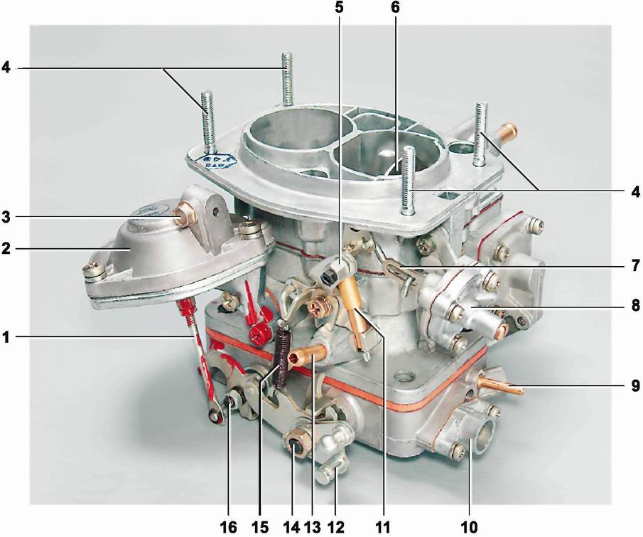
1 - pneumatic actuator throttle of the secondary chamber; 2 - pneumatic drive of the throttle of the secondary chamber; 3 - Bolt fastening the shell of the drive of the air damper drive; 4 - heel fastening the air filter housing; 5 - Coupling with an air damper drive thrust mounting screw; 6 - air damper; 7 - trunk diaphragm rod; 8 - starting device; 9 - nozzle connected to a vacuum regulator of the ignition distributor; 10 - quality screw holder; 11 - Telescopic thrust; 12 - throttle drive lever; 13 - Carter gases removal nozzle; 14 - axis of throttle valve primary chamber; 15 - Return spring blocking opening the valve of the secondary chamber; 16 - axis of the throttle of the secondary chamberCarburetor - emulsion type, two-chamber, with a falling flow. The combustible mixture is formed from an air filter of air and fuel supplied by the pump. This ensures uninterrupted supply of a combustible mixture of optimal composition on all modes of engine operation. The prepared mixture is absorbed through the inlet pipeline into the engine cylinders. The carburetor consists of three cabinet parts: covers, carburetor housing and throttle housing.
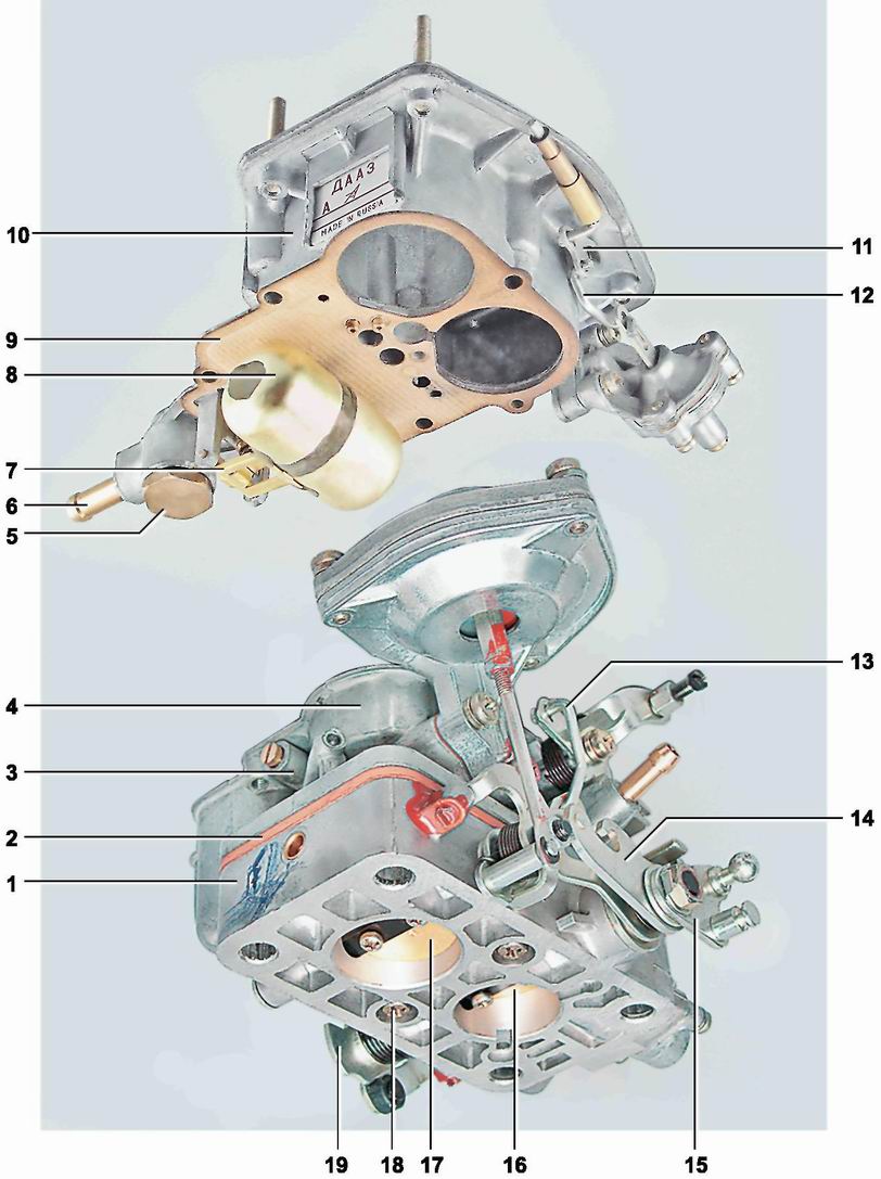
Cover and carburetor housing 2105-1107010-20:
1 - throttle housing; 2 - thermally insulation spacer; 3 - fuel oil body of the secondary chamber transition system; 4 - carburetor housing; 5 - cork fuel filter carburetor; 6 - fuel pipe; 7 - needle valve housing; 8 - float; 9 - gasket; 10 - carburetor cover; 11 - air damper lever; 12 - thrust connecting the arm of the air damper with the rod of the trigger diaphragm; 13 - thrust valve link with trigger drive; 14 - lever limiting the opening of the throttle of the secondary chamber; 15 - throttle drive lever; 16 - throttle valve primary chamber; 17 - throttle valve of the secondary chamber; 18 - screw fastening of throttle housing; 19 - Fist Drive Acpercelative PumpThe carburetor is installed on four heels of the inlet pipeline. In the lid of the carburetor, there are inlets of primary and secondary mixing chambers, fuel supply fitting from the fuel pump, fuel and air channels. A needle fuel supply valve and a float that provide the required level of fuel in the float chamber is also fixed on the lid. In the carburetor housing, large diffusers and a float chamber are made.
In the carburetor housing, air and fuel channels are made, air and fuel jets are installed, the sprayer of the accelerator pump.
The accelerator pump provides an additional portion of fuel into the primary mixing chamber with a sharp press of the gas pedal. The diaphragm type pump is made in the bondage of the housing and is closed with a lid fixed by four screws. The diaphragm of the pump is moving by the lever. To ensure the smoothness of the stroke and, accordingly, smooth and long-term injection in the telescopic glass of the diaphragm installed a damping spring. The accelerator pump lever is driven by a cam fixed on the axis of the primary chamber's throttle.
On the bottom to the carburetor body with two screws, the throttle housing is mounted. It has rotary throttle valves on the axes in the primary and secondary mixing chambers. The throttle valve of the primary chamber is carried out mechanically through the system of adjustable thrust from the "gas" pedal. The throttle valve of the secondary chamber is pneumatic. The body of the drive, with a diaphragm and spring reverse stroke, is fixed on the carburetor body with two screws. The drive stock is hinged with the lever on the axis of the throttle of the secondary chamber. The pneumatic acceptor begins to open it when the throttle valve rejects the primary chamber at an angle of more than 48 ° and when creating a vacuum in mixing chambers sufficient to open the damper.
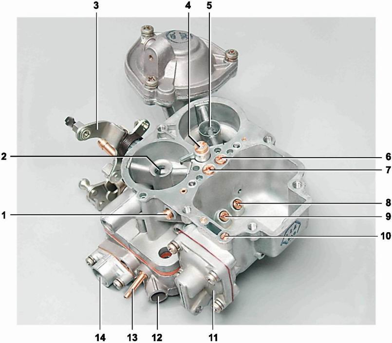
Case carburetor 2105-1107010-20:
1 - housing of the fuel gibber system of idle; 2 - small diffuser primary chamber; 3 - three-meter lever; 4 - accelerator pump sprayer; 5 - small diffuser of the secondary chamber; 6 - the main air jet of the secondary chamber; 7 - the main air jet of the primary chamber; 8 - the main fuel jet of the secondary chamber; 9 - the main fuel jet of the primary chamber; 10 - Adjusting fuel supply screw accelerating pump; 11 - the cap of the accelerator pump; 12 - adjusting screw of the composition (quality) of a mixture of idling; 13 - discharge fitting to a vacuum ignition distributor regulator; 14 - Adjusting screw of the amount of a mixture of idlingTo start and running the engine when heating in the carburetor, there are a starting device and an air damper. The air damper is installed on the axis in the inlet neck of the primary chamber of the carburetor cover. The drive of the flap is carried out from the driver's seat with a cable from the control handle. The trigger case is fastened with two screws to the lid of the carburetor. The trigger drive rod of the starting device is connected by the air damper lever. The cavity of the starter is connected by the aircraft with the primary mixing chamber. When the engine is started in the cavity, there is a vacuum. The rod of the diaphragm is pressed the return spring, affects the thrust and opens the air damper.
The idle adjustment is carried out by the composition (quality) screws and the amount of the mixture.
Until 1976, carburators were installed on the car 21011107010, 2101-1107010-02, from 1997 to 1979. - Carburetor 2101-1107010-03. These carburetors have the same device and differ mainly by dosing elements. The carburetors are made with a non-autonomous idling system and the mechanical drive of the throttle valve of the secondary chamber. In the throttle housing of the carburetors there is a channel of heating the idle system. Carburators 2101-110710, 2101-110710-02 have a valve of foaming chamber. The carburetor 2101-110710-03 the hole for the output of the emulsion from the idle stroke system is located in the throttle body between the primary and secondary mixing chambers.
Table 8.2.1. Carburators target data
|
Parameters |
Carburetor |
||||
|
Mixing Camera Primary / Secondary |
|||||
|
Diameters, mm: |
|||||
|
diffuser |
|||||
|
main fuel gibler |
|||||
|
the main air gibler |
|||||
|
idling fuel gibler and transition system |
|||||
|
air jigger idling and transition system |
|||||
|
acpercement Pump Sprayer Holes |
|||||
|
exposure Jicker Accelerator Pump |
|||||
|
fuel gibber econostata |
|||||
|
air gibber eco-status |
|||||
|
emulsion gibber Economist |
|||||
|
punk Air Gibrel |
|||||
|
gibler Pneumatic Drift Throttle Performing Camera |
|||||
|
Spray targeting number |
|||||
|
Emulsion tube calibration number |
|||||
|
Feeding the accelerator pump for 10 full moves, cm³ |
|||||
|
Distance float from the carburetor cover with a gasket, mm |
|||||
|
Clamps dampers for adjusting the starting device, mm: |
|||||
|
air damper |
|||||
|
throttle valve |
|||||


