Features of the design of the intermediate shaft, the cardan transmission, the actuator shaft of the leading bridges Chevrolet Niva
Complexity
Without toolsNot indicated
Instruments:
Details and consumables:
- Oil filter
- Motor oil
- Rag
Note:
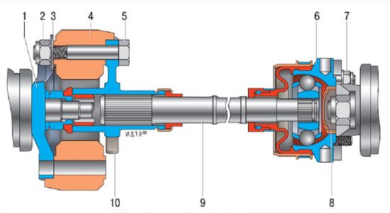
The cardan transmission is designed to transmit torque from the gearbox to the transfer box and from the transfer box to the front and rear leading shafts.
Cardan transmission:
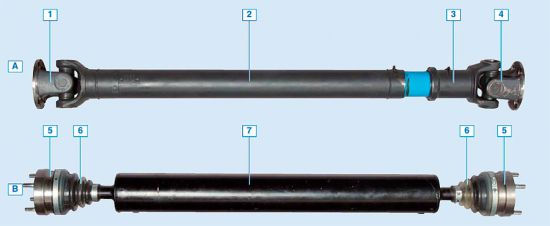
1
- front cardan shaft;
2
3
- transfer case;
4
- Rear cardan shaft.
The Carian Transmission of the VAZ-2123 car consists of intermediate 2, front 1 and rear 4 cardan shafts.
Intermediate cardan shaft:
1
- Flange of the secondary shaft of the gearbox;
2
- Nut;
3
- balancing washers;
4
- elastic coupling;
5
- bolt fastening flange;
6
- hinge housing of equal angular velocities;
7
- Nut;
8
- plug hinge housing;
9
- intermediate cardan shaft;
10
- Elastic coupling flange.
Torque from the transfer box to the front and rear leading bridges is transmitted by the drive shafts. Front and rear shafts by car are the same in design and interchangeable. On the restyled car, drive shafts of an improved structure are used, and since May 2010, the actuating shafts with hinges of equal angular velocities went to the series.
The design of the cardan shaft on a restyled car is changed compared to previous versions of the machine.
Trees drive leading bridges:
BUT - Cardan shaft;
IN- shaft with hinges of equal angular velocities;
1
- shaft flange;
2
- Truck shaft;
3
- sliding fork;
4
- Flange of the sliding fork;
5
- constant-velocity joint;
6
- Blanker of the hinge;
7
- Truck tree.
The cardan shaft is a steel pipe, to which the plug of the cardan hinge is welded on one side, and on the other hand, a profiled hole is placed under the sliding tip of the moving plug of the second hinge. The slotted connection is compacted by a non-removable gland mounted on a sliding fork. The dimensions of the slotted compound (diameter, number and height of the teeth) compared with the previous version are significantly increased. The size of the locking rings is also enlarged, as well as the diameter of the spikes of crosses and cups of bearings. In addition, instead of fastening bolts with a round head and lodge, standard bolts with a hex head turnkey "on 13" are used.
Both cardan hinge at the ends of the shaft are connected to the flanges, one of which (from the side of the sliding fork) shaft is attached to the flange of the transfer box, and the other to the flange of the gearbox of the leading bridge. The cardan shaft assembled with the flanges is dynamically balanced on special stands; The imbalance is balancing the welding of balancing plates to the tree tube. When disconnected parts of the cardan shaft, you need paint or core to apply the labels of the mutual location of the parts to install them in the correct position when assembly.
The drive shaft must be anewly balancing with the loss of balancing plates, when replacing the parts of the cardan transmission (sliding fork, the flange, in some cases - crosses with bearings), as well as during deformation (in the latter case, balancing is carried out after elimination of deformation). If balancing does not help eliminate vibrations, the cardan shaft assembly replaces the new one.
If when replacing the crossing, it was not necessary to pick up new locking rings, then you can do without balancing. Otherwise, the imbalance leads to a noticeable increase in the level of vibrations in speed at speeds of more than 60-80 km / h. It is also possible to destroy the cardan transmission and connected to it the aggregates of the car.
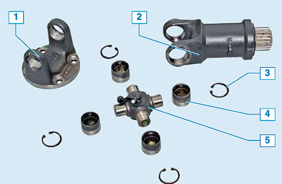
Cardan connection elements:
1
- the flange of the cardan hinge;
2
- sliding fork of the cardan shaft;
3
- retaining ring;
4
- cup of bearing with needles and glands;
5
- Cross.
The cardan hinge consists of two forks, interconnected by cross-casket on bearings. Four cups of radial bearings with needles (thin rollers) are put on the spikes of crosses. To protect against dirt, bearings are compacted by plastic glands. A plastic washer is installed between the bearing housing and the end of the schip, which prevents the heating of the node and the "welding" of lubrication. To replenish lubrication in crosses, molds are installed, the lubricant is laid in the slot connection during the assembly and is replenished when servicing the cardan shaft.
As a lubricant of crossing bearings, a grease lubricant Litin-2 or Fiol-2 y is used, for lubricating a slot compound - grease No. 158 or LSC15. You can also use imported analogues that are sold both in regular containers and in standard tubes for the syringe of the cardan shaft press oil. After pressing the casket bearings of the bearing (the pressing force should not exceed 1500 kgf), the locking rings must be tightly included in the grooves intended for them in the holes of the forks and flanges. If necessary, you can slide new locking rings a bit if they are not included in the duct (in this case, the balancing shaft must be required).
After installing the locking rings, we hit the hammer with a plastic booler with a plastic bolt (or a conventional hammer through a wooden spacer) so that the bearing cups cluttered tightly to the locking rings. The correctly assembled bearing rotates easily and without jealous, and at the same time should not have a tangible backlash (as the clearance is very small, and also a cup of bearing is suppressed by the gland).
Since May 2010, the plant began to use in the transmission instead of the cardan shafts of the classical design, the egregated drive shafts, at both ends of which are hinges of equal angular velocities (shoes). This made it possible to significantly reduce the level of vibrations arising when the car moves. With a general similarity of the design, these shruses by execution are somewhat different from the shruses used in the drive of the front leading wheels and on the intermediate shaft of the transmission.
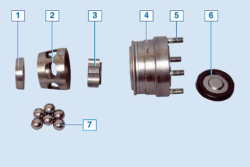
Hinge elements of equal angular velocities:
1
- centering washer;
2
- separator;
3
- internal clip;
4
- hinge body with external clip;
5
- connecting heel;
6
- plug of the inner cavity of the hinge;
7
- balloons.
Mutual axial movement of the parts of the drive shaft with the shurts is minimal, there are no movable slotted connections in its design. Required for the work of the rear suspension The free course of the shaft details is ensured by the design of the shruses. Because of this, the process of removing the shaft from the machine and install it is difficult to remove it, because you have to remove the dispensing box with the fixture studs.
The inner clip of the hinge is fixed from the axial movement with a spring retaining ring located in a ring roller at the end of the shaft. The inner part of the hinge is protected from dirt from entering and throwing a lubricant with an elastic corrugated cover and a stub with a rubber seal. The plug closes the hole in the end of the hinge housing. The case is fixed on the shaft and the hinge body with special reusable clamps with fixing locks.
The article lacks:
- Quality photos


