Device and design, specifications, maintenance
Carburetor VAZ2101, carburetor device
Engine carburetor 2101 and 21011. Two-chamber vertical carburetor (Fig. 82) is installed on VAZ vehicles (Fig. 82) with a consistent discovery of chokes. The throttle drive of the secondary chamber mechanical and is carried out by the lever system from the primary camera choke.
The carburetor is equipped with an automatic starting device, a diaphragm accelerating pump and a valve of the unbalance of the float chamber. On the axis of the primary chamber, the spool of the engine crankcase ventilation system is installed; The enclosures of the chokes in the inside of the idle channels has heated from the engine cooling system.
Fig. 82. Carburetor: A - view of the carburetor body with a lid removed; 1 - screw adjustment of the composition of the mixture; 2 - idle bicker housing; 3 - main air jets; 4 - plug valve pump-accelerator; 5 - main jets; 6 - Valve of the pump accelerator sprayer; 7 - air jets of the idle system; b - view of the cover of the carburetor housing; 1 - Valve of the Float Camera Unbalance; 2 - fuel supply pipe to the carburetor; 3 - Cover of the fuel filter of the carburetor; 4 - float; 5 - eco-beer fuel oil; 6 - ehonostat emulsion jicker; 7 - Air damper
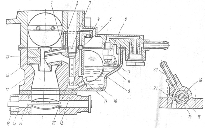
Fig. 83. Main dosing system, eco-statute, spool device: 1 - ehonostat emulsion jet; 2 - Emulsion channel of eco-statute; 3 - air jaw the main dosing system; 4 - Economy Air Juger; 5 -to-fuel bicker eco-statute; 6 - needle valve; 7 - axis float; B - needle valve ball; 9 - float; 10 - Float Camera; 11 - the main jib; 12 - emulsion well; 13 - emulsion tube; 14 - axis of the choke of the primary chamber; 15 - spool groove; 16 - spool; 17 - big diffuser; 18 - small diffuser; 19 - sprayer; 20 - tube of trimming of crankcase gases; 21 - Calibrated Hole
In 1974, carburetors were used on cars 2101-110701.0-02. Reduce the content of carbon monoxide in the exhaust engine gases. These carburetrators differ from the usual 2101-1107010 diameters of jams (Table 4). By car BA3-2103, a carburetor is installed with a spilling valve for overlapping idling channels when the ignition is turned off and has a modified targeting. Therefore, it will be discussed below.
Main dosing system. Fuel through the needle valve 6 (Fig. 83) enters the float chamber 10; Float 9, installed on axis 7, supports the required fuel level. From the float chamber, the fuel through the main jets 11 enters the emulsion well 12, mixed with air, coming out of the holes of the emulsion tubes 13 and entering them through air jets 3. Then through the sprayers 19 fuel gets into small 18 and large "" carburetor diffusers.
The main air jets 3 primary and secondary chambers appearance are the same. They differ in marking, knocked out on the upper plane of the gibera head (for example, 170 or 190), which denotes the diameter of the bike hole (1.70 or 1.90 mm).
The main fuel jets 11 labeling is applied on the side surface of the head (135 or 125) and also denotes the diameter of the bike hole (1.35 or 1.25 mm).
The emulsion tubes 13 of the primary and secondary chambers at the carburetor car VAZ-2101 are the same. However, on other models of cars they can be different. Therefore, on a cylindrical surface at the bottom of the tubes, marking (for example, 15) is applied, which indicates the calibration number number. On small diffusers 18 there are also marked (for example, 4 or 4.5), denoting the target number of the sprayer of the sprayer 19.
The processing device (econostat). The carburetor has a rich device included in the secondary chamber. The fuel from the float chamber through the fuel oil 5 enters the channels of the econostat, located in the cover of the carburetor housing, where the air entering it, which goes through the jigger 4. The air emulsion over the channel 2 passes through the calibrated hole of the gibber /, enters the small spray channel and Diffuser 18. EcoPostat enters work on high-speed modes close to the maximum with fully open chokes.
The spool device of ventilation map-R A includes a spool 16, sitting on the axis 14 of the primary camera choke. The tube 20 is connected to the engine crankcase ventilation system and can be communicated with the cavity opened into the axle space. The device is described in the section<Система вентиляции картера двигателя>.
The throttle drive (Fig. 84) works as follows. When exposed to throttle control pedal drive (not shown in the diagram) on the lever 11, the lever, the primary camera, rigidly sitting on the axis of the throttle axis, rotates counterclockwise, the choke begins to get off. Sector 13, which is rigidly sitting on the axis, is also rotated, with its protrusion 12, turning along with the axis, passes some plot until it strives to the intermediate lever 16, the finger of which is included in the lever groove 1 "91 sitting on the throttle axis The secondary chamber. With the further turn of the axis of the primary camera, the protrusion 12 turns the lever 16, which in turn, through the lever 19 begins to open the throttle of the secondary chamber. The ratio of the three levers is chosen so that the choke of the secondary chamber opens after the primary camera choke It will turn to an angle of 48 °. In the position of the full discovery of chokes come simultaneously.
The starting device serves to start a cold engine. When pulling the button starter (located under the instrument panel), a three-way lever 1, turning around its axis, occupies a position A, simultaneously operating with a throttle 22 and lever 21 primary camera choke.
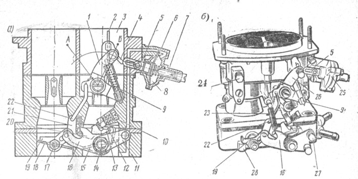
Fig. 84. Startup and throttle drive: 1 - air damper control lever; 2 - the air damper of the starting device; 3 - air nozzle of the primary chamber of the carburetor; 4 - traction; 5 - rod; 6 - diaphragm; 7 - adjusting trigger screw; 8 - the cavity communicating with the bumps; 9 - Telescopic thrust; 10 - the adjusting screw of the choke of the camera; 11 - throttle control lever; 12 - protrusion; 13 - sector; 14 - axis of the choke of the primary chamber; 15 - choke primary chamber; 16 - intermediate lever drive throttle camera; 17 - the axis of the choke of the secondary chamber; 18 - throttle of the secondary chamber; 19 and 21 - levers; 20 - protrusion of the intermediate lever; 22 - thrust binding a primary camera choke with a trigger drive; 23 - Return spring lever drive lever secondary chamber; 24 - bolt attaching a starting device drive cable; 25 - trigger diaphragm case; 26 - air damper control lever; 27 - ball finger lever drive lever primary chamber; 28 - Screw adjustment of the position of the throttle of the secondary chamber; A - position of the lever 1 at startup; B - lever position 1 during engine operation
Telescopic thrust 9 acts on the lever, motionless sitting on the axis of the air damper. The air damper 2 is closed, and the end of the thrust 4, moving into the rod rod 5, occupies an extreme left position. At the first outbreaks and the subsequent operation of the engine at idle, the vacancy from the bonding space is transmitted to the cavity 8. The diaphragm 6, acting through the rod 5 on the craving 4 and the lever, opens the air whores the opening limits of the air damper, ensuring the absence of excessive enrichment or depletion of the mixture in The engine is adjusted by the bending of the thrust 4 and the rotation of the adjusting screw 7.
When you start a cold engine, you should turn on the fully starting device, pulling up the control button to fail. You can not press the throttle control pedal even if the engine is not allowed. This will be excluded overflowing fuel.
After starting when driving the engine, it is gradually turned off the starting device providing steady operation of the engine, and when the engine completely warms off the starting device, returning the control button to its original position, while the lever 1 occupies the position of the air damper completely opens.
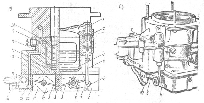
Fig. 85. The idle system and the foaming chamber unbalance valve: A -Cheme; B - view on the carburetor from the side of the valve focallery of the float chamber; 1 - channel reporting a float chamber with an atmosphere; 2 - valve; 3 - Float Camera; 4 - rod; 5 - intermediate lever; b - the carburetor housing; 7-secondary mixing chamber; 8 - choke of the secondary chamber; 9 is a primary camera; 10) -Rechag drive pump accelerator with emphasis A; 11- primary mixing chamber; 12 - hole. adjustable screw; 13 - openings of transition modes; 14 - adjusting screw; 15 - Channel heating of choke housing; 16 - emulsion well; 17 - emulsion channel of the idle system; 18 - the fuel channel of the idle system; 19 - Fuel journey of the idle system; 20 - air jet of idle system; A - emphasis; B - Spring Intermediate Lever Drive Valve Expansion
The idle system (Fig. 85) is included at the main jet. The fuel from the emulsion well 16 through the channel 18 goes to the 15 idle gibber, mixed with air entering through the air javel 20, and on the channel 17 goes to the hole 12, open into the axes. The hole in the hole is adjustable by screw 14. The location of the holes 13 provides the absence of failures in the engine operation at the opening of the choke.
The secondary chamber includes a system, differing from the idle chamber system in the absence of an adjusting screw 14 and holes 12. The specified system ensures the absence of failures in the engine operation at the time of opening the choke of the secondary chamber and is called the transition system. The transition system is turned on directly into the float chamber.
On the cylindrical belt of fuel jams 19 there is marking (for example, 45 or 60), indicating the diameter of the fuel jet holes (0.45 or 0.60 mm).
Floating Camera Unbalance Valve. Under the positions of the primary chamber throttle corresponding to the low idling turnover, the lever 10 of the pumping of the pump-accelerator focusing A (see Fig. 85, a) holds back the spring-loaded lever 5. Valve 2, pressing the spring to the rod 4, is in the extreme lower position, and Float Camera 3 through the channel 1 reported with the atmosphere. When turning the throttle towards the opening, the stop and frees the lever 5, which turns under the action of the spring B (according to the circuit counterclockwise) and, acting through the rod on the valve, closes it. The float chamber at the same time disaggregated with the atmosphere.
The valve is used to facilitate the start of the hot engine, preventing fuel vapor entering the engine input path, which can lead to excessive enrichment of the mixture and, therefore, to a difficult start.
Heated housing of chokes. In the cold season, ice on the elements of the carburetor, located in the zone of throttling gap of the primary chamber flap, was introduced on the carburetor, the heated zone of the idle channels from the engine cooling system was introduced. The nozzles of the input 16 and the output 18 are shown in Fig. 86, b.
Pump accelerator (Fig. 86). When opening the primary chamber choke, the lever 6, sitting on its axis turns, and through the lever 7 acts on the spring-loaded end of the cup 9. The diaphragm 10, overcoming the return spring 8, pushes the fuel from the cavity and in the channel 3, the ball valve screw / and through Sprayer 2 - in the diffuser of the primary chamber of the carburetor. The valve 11 is closed.
The sprayer 2 has marked (for example, 40), indicating the diameter of the spray hole (0.40 mm).
The bypass jigger 4 is selected in such a way that with a sharp movement of the diaphragm, the required mode is provided
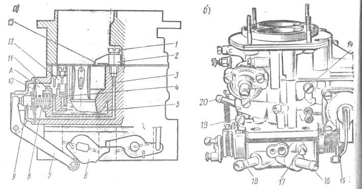
Fig. 86. Pump accelerator: A - diagram; b - view of the carburetor from the pump-accelerator; 1 - ball valve screw; 2-accelerator pump sprayer; 3 - fuel channel; 4 - bypass jigger; 5 - Float Camera; 6 and 7- levers drive accelerator pump; 8-recurring pump spring; 9 - a cup of diaphragm; 10 - pump diaphragm; 11 - inlet ball valve; 12 - camera vapor pump; 13 - housing of the fuel gibber system of idle; 14 - case of an emulsion jicker system of idle; 15 - pump-accelerator cover; 16 - inlet pipe of heating of choke housing; 17 - screw adjustment of the composition of the mixture at idle engine; 18 - the outlet nozzle of heating the choke housing; 19 - screw regulating the opening of the primary chamber choke; 20 - Carter gas supply pipe to spool device
engine operations, and during a smooth during the diaphragm or its oscillations on an uneven road, all the fuel dispensed with a diaphragm enters the float chamber without disturbing the desired engine operation mode.
The lever profile 6 is designed so that the pump performs a double fuel injection, and the second injection coincides with the moment of opening the choke of the secondary chamber
The drive control of the carburetor. The drive control of the carburetor chokes lever, and the air damper - the cable. The chokes are driven from the pedal 9 (Fig. 87), hingedly fixed on the floor of the cabin. The pedal through the sleeve 8 acts on the lever, welded to the roller 12. The roller rotates in two plastic brackets 13 attached to the shield of the car front.
Two more levers - 11 and 14 are welded to the roller. Spring 10 is attached to the lever 11, and the lever 14 through the longitudinal craving 2, the lever 15 and the transverse craving 1 is associated with the lever 11 (see Fig. 84) of the throttle drive.
In the intake pipeline, the screw 16 wocks (see Fig. 87), for which the spring is clinging 17. The lever 15 rotates on the axis welded to the cylinder head cover. Traction 1 and 2 have plastic threaded tips.
With a fully pressing pedal 9, chokes must be fully open and throttle levers should not have an additional stroke. If this is not, then you can align the position of the pedal and chokes by changing the length of the thrust 2, unscrewing or taping it.
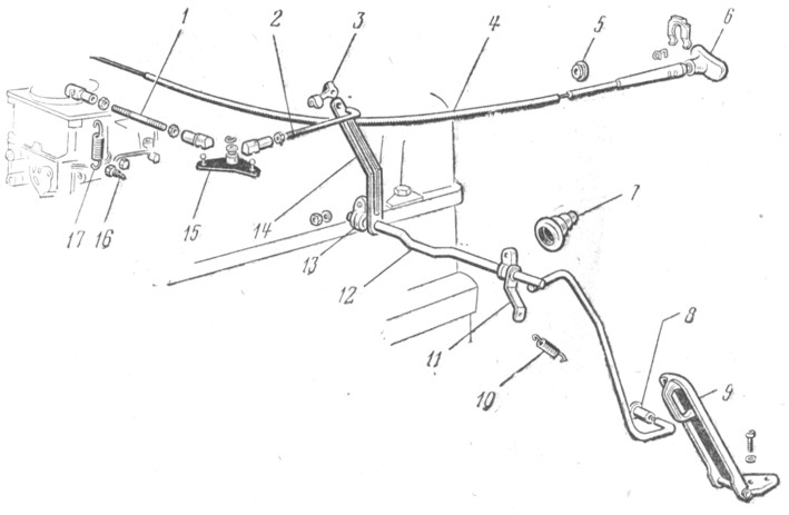
Fig. 87. Carburetor control drive: 1- cross traction: 2 - longitudinal traction; 3 - traction mounting bracket; 4- air damper control; 5 and 7 - seals; 6 - air damper control cable 8 - sleeve; 9 - throttle control pedal; 10 - Returning spring; 11 and 14 - screw fastening of a return spring: 13 - Bracket mounting roller; 15 - intermediate lever; 16 - Returning Springs; 17 - Returning Spring
The air damper is controlled by a cable 4, the handle 6 of which is under the instrument panel. The cable shell is attached to the carburetor with bolt 24 (see Fig. 84, b), and the end of the cable is attached to the air damper control lever 26.
The cable and its shell must be fixed so that with a fully elongated handle 6 (see Fig. 87) the air damper was completely closed, and with a recessed handle - fully open.


