VAZ 2107 1982+ Reducer
Definition gear failure by noise
Carry out troubleshooting in the following order:
Challenge #1. To clearly identify the nature of the noise, drive along the highway at a speed of approximately 20 km/h.
Then gradually increase the speed up to 90 km/h, listening at the same time for different types of noise and noticing the speed at which they appear and disappear.
Release the throttle pedal and, without braking, dampen the engine speed.
During deceleration, watch the noise change, as well as the moment when the noise increases. Normally, the noise comes and goes at the same speeds both when accelerating and when decelerating.
Test #2. Accelerate the vehicle to approximately 100 km/h, put the gearshift lever in neutral, turn off the ignition and allow the vehicle to roll freely to a stop; watch the noise pattern at different deceleration rates.
The noise noticed during the test and consistent with that noticed during the first test does not come from the final drive gears, since they cannot make noise when unloaded.
Conversely, noise noted on the first test and not repeated on the second may come from the gears of the gearbox or the bearings of the pinion or differential.
Test number 3. With the car stationary and braked, turn on the engine and, gradually increasing its speed, compare the noises that have arisen with those noticed in previous tests. Noises found to be similar to those of test #1 will indicate that they are not gearbox noise in test #1 and are caused by other components.
Test No. 4. Noises found during the first test and not repeated during subsequent ones come from the gearbox; to confirm, lift the rear wheels, start the engine and shift into fourth gear. In this case, you can make sure that the noises really come from the gearbox, and not from other components, such as suspension or bodywork.
Removing the gearbox
If necessary, remove only one gearbox:
Drain the oil from the bridge beam;
Raise the rear of the car, place it on stands and remove the wheels;
Unscrew the nuts securing the brake shield to the beam and extend the axle shafts so that they come out of the differential box;
Disconnect the cardan shaft from the gearbox, place a stand under the gearbox housing, unscrew the bolts of its fastening to the rear axle beam and remove the gearbox from the beam without damaging the gasket.
Installing the gearbox
Before installing the gearbox, thoroughly clean the axle beam from oil.
Place a sealing gasket on the mating surface, insert the reducer into the beam and fasten it with bolts. Lubricate the threads of the bolts with sealant. Thoroughly degrease the bolts and holes in the beam before applying the sealant. Attach the cardan shaft to the gearbox. Install axle shafts and brake drums.
Install the wheel with the tire and tighten the wheel bolts without tightening. With both wheels in place, remove the stands and lower the car; then tighten the wheel bolts with a torque wrench.
Fill the axle beam with oil through the oil filling hole, having previously cleaned and screwed the magnetic drain plug into the beam.
Gearbox disassembly
Fix the reducer on the stand. Remove the locking plates 9 (see Fig. 4–63), unscrew the bolts and remove the differential box bearing caps, adjusting nuts, and the outer races of the roller bearings. Mark the covers before removing them so that they can be installed in their original places during assembly.
Remove the differential case from the gearbox housing together with the driven gear and inner bearing races.
To remove the drive gear and its parts:
Turn the gearbox housing over with the neck up (Fig. 4–64) and, holding the flange 3 of the drive gear with the stopper 1, unscrew the flange fastening nut with the key 2;
Remove the flange and take out the drive gear with the adjusting ring, the inner ring of the rear bearing and the spacer sleeve;
Remove the oil seal, oil deflector and the inner ring of the front bearing from the gearbox housing;
Press out the outer races of the front and rear bearings using drift A.70198;
Remove the spacer sleeve from the drive gear and, using the universal puller A.40005/1/7 and mandrel A.45008 (Fig. 4–65), remove the inner ring of the rear roller bearing;
Remove the drive gear adjusting ring.
To disassemble the differential:
Remove the inner rings 2 (Fig. 4–66) of the roller bearings of the differential box 3, using the universal puller A.40005/1/6 and stop A.45028 for this;
Unscrew the fastening nuts of the driven gear and knock out the axis of the satellites from the box;
Turn the gears of the axle shafts and satellites so that the latter roll out into the windows of the differential, after which they can be removed;
Remove the axle gears with thrust washers.
Examination technical condition gear parts
Rinse thoroughly before inspecting gearbox parts. This will make it easier to detect wear and damage to parts.
Check whether there are any damages on the teeth of the final drive gears and whether the contact spots on the working surfaces of the teeth are correctly located. In case of unacceptable wear, replace the parts with new ones; if the engagement is incorrect, find the cause.
Check up a condition of apertures of satellites and surfaces of their axis; in case of minor damage to the surface, sand with fine-grained sandpaper, and in case of serious damage, replace the parts with new ones.
Check the surfaces of the journals of the gears of the axle shafts and their mounting holes in the differential box, repair the damage as in the previous operation.
Check the surfaces of the bearing washers of the gears of the axle shafts, repair even minor damage. When replacing washers, select new ones according to their thickness.
Inspect the roller bearings of the drive gear and differential box; they must be wear-free, with smooth working surfaces. Replace bearings at the slightest doubt about their performance, poor bearing condition can cause noise and seizing of teeth.
Check for deformations or cracks on the crankcase and on the differential box, if necessary, replace them with new ones.
Gear Assembly
Reliable operation of the gearbox is ensured by strict adherence to the following assembly and adjustment procedures.
|
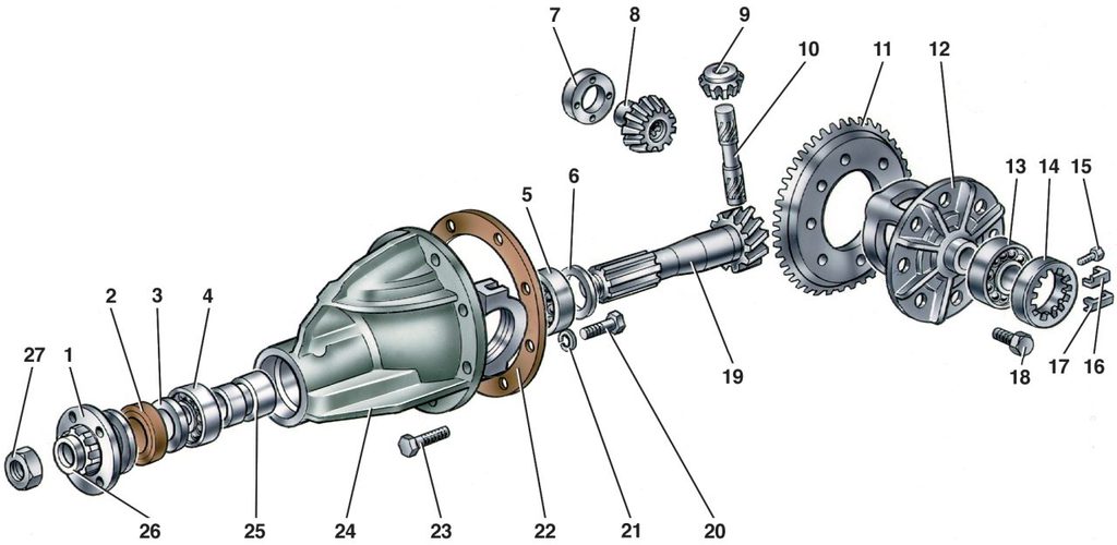
| Rice. 4–67. Details of the rear axle gearbox: 1 - drive gear flange; 2 - stuffing box; 3 - oil deflector; 4 - front bearing; 5 - rear bearing; 6 - adjusting ring of the drive gear; 7 - support washer of the axle gear; 8 - axle gear; 9 - satellite; 10 - satellite axis; 11 - driven gear; 12 - differential box; 13 - differential box bearing; 14 - adjusting nut; 15 - a bolt of fastening of a locking plate; 16 - locking plate; 17 - locking plate; 18 - bolt for fastening the driven gear to the differential box; 19 - drive gear; 20 - cover fastening bolt; 21 - spring washer; 22 - gasket; 23 - a bolt of fastening of a reducer to a beam of the back bridge; 24 - gearbox housing; 25 - spacer sleeve; 26 - flat washer; 27 - a nut of fastening of a flange of a leading gear wheel |
Differential Assembly. Lubricate with gear oil and install through the windows in the differential box the gears of the axle shafts with support washers and satellites. Turn the satellites and gears of the axle shafts so as to align the axis of rotation of the satellites with the axis of the hole in the box, then insert the axis of the satellites.
Check the axial clearance of each axle gear: it should be 0–0.10 mm, and the moment of resistance to rotation of the differential gears should not exceed 14.7 N m (1.5 kgf m).
If the clearance is increased, which is a sign of wear of the differential parts, replace the bearing washers of the gears of the axle shafts with others of greater thickness. If the specified clearance cannot be obtained even with the thickest washers installed, replace the gears with new ones due to excessive wear.
Install the driven gear on the differential case.
Using mandrel A.70152, press the inner races of roller bearings onto the differential box.
Installation and adjustment of the drive gear. The correct position of the drive gear relative to the driven gear is ensured by selecting the thickness of the adjusting ring installed between the thrust end of the drive gear and the inner ring of the rear bearing.
Select the adjusting ring using the mandrel A.70184 and tool A.95690 with indicator. Perform operations in the following order.
Having fixed the gearbox housing on the stand, press the outer rings of the front and rear bearings of the drive gear into the crankcase sockets, using mandrels for this: for the front bearing - A.70185, and for the rear - A.70171 (Fig. 4–68).
On mandrel A.70184, simulating the drive gear, use mandrel A.70152 to install the inner ring of the rear bearing and insert the mandrel into the neck of the gearbox housing (Fig. 4–69).
Install the inner ring of the front bearing, the drive gear flange and, turning the mandrel to properly install the bearing rollers, tighten the nut to a torque of 7.8–9.8 N m (0.8–1 kgf m).
Fix fixture A.95690 on the end of mandrel 4 and adjust the indicator, which has divisions of 0.01 mm, to the zero position by placing its leg on the same end of mandrel A.70184. Then move indicator 1 so that its leg rests on the seating surface of the differential box bearing.
Turning the mandrel 4 with the indicator to the left and right, set it to a position in which the indicator needle marks the minimum value "a1" (Fig. 4–70) and write it down. Repeat this operation on the seat of the second bearing and determine the value "a2".
Determine the thickness "S" of the drive gear adjusting ring, which is the algebraic difference between the values "a" and "b":
where a is the arithmetic mean distance from the ends of the mandrel 1 (Fig. 4–70) to the necks of the differential bearings
a = (a1 + a2) / 2,
b - deviation of the drive gear from the nominal position, translated in mm. The deviation value is marked on the drive gear (Fig. 4–71) in hundredths of a millimeter with a plus or minus sign.
When determining the thickness of the adjusting ring, take into account the sign of the value "b" and its unit.
Example. Let us assume that the value "a", set using the indicator, is equal to 2.91 mm (the value "a" is always positive), and the deviation "-14" is set on the drive gear after the serial number. To get the value of "b" in millimeters, you need to multiply the indicated value by 0.01 mm.
If the moment of resistance to rotation is less than 157 N cm (16 kgf cm), and for bearings after a run of 30 km or more - 39.2 N cm (4 kgf cm), then tighten the drive gear flange nut (without exceeding the specified torque tightening) and recheck the moment of resistance to turning the drive gear.
If the torque is greater than 198 Ncm (20 kgfcm) or 58.8 Ncm (6 kgfcm) for worn-in bearings, indicating that the bearing preload is too high, replace the spacer with a new one as it is too tight. load has deformed to a size that does not allow for correct adjustment. After replacing the spacer sleeve, repeat assembly with appropriate adjustments and checks.
Box installation differential
Install the pre-assembled differential case in the crankcase together with the bearing outer races.
Rice. 4–76), and install the bracket 4 so that the indicator leg 2 rests on the side surface of the driven gear tooth at the edge of the tooth, then tighten the screws 1 and 3.
By turning the adjusting nuts, pre-adjust the backlash between the teeth of the driving and driven gears within 0.08–0.13 mm. The gap is checked by indicator 2 while rocking gear 6. In this case, the bearings should not have a preload. The adjusting nuts must only be in contact with the bearings, otherwise the correct preload measurement will be impaired.
Consistently and evenly tighten the two adjusting nuts of the bearings, while the differential bearing caps diverge and, therefore, the distance "D" increases (Fig. 4–77). This discrepancy is noted by indicator 9 (Fig. 4–75), on the leg of which lever 5 acts. The nuts for adjusting the bearings of the differential box are tightened to increase the distance "D" (Fig. 4–77) by 0.14–0.18 mm.
Having set the exact preload of the bearings of the differential box, finally check the backlash in the meshing of the final drive gears, which should not change.
If the gap in the meshing of the gears is more than 0.08–0.13 mm, then move the driven gear closer to the drive gear or move it away if the gap is smaller. To maintain the set bearing preload, move the driven gear by tightening one of the bearing adjusting nuts and loosening the other by the same angle.
To accurately perform this operation, follow indicator 9 (Fig. 4–75), which shows the value of the previously set bearing preload. After tightening one of the nuts, the indicator reading will change, as the discrepancy "D" (Fig. 4-77) of the covers and the preload of the bearings will increase. Therefore, loosen the other nut until the indicator needle returns to its original position.
After moving the driven gear, on the indicator 2 (Fig. 4-76) check the amount of side clearance. If the clearance is not correct, repeat the adjustment.
Remove tool A.95688/R, install the locking plates of the adjusting nuts and secure them with bolts and spring washers. Spare parts are supplied with locking plates of two types: with one or two legs, the plates are installed depending on the position of the nut slot.
The adjustment and repair of the gearbox units is carried out on the stand, where you can also test the gearbox for noise and check the location and shape of the contact patch on the working surfaces of the teeth, as indicated below.
Contact check working surface gear teeth main gear
For the final check on the stand of the quality of the gear engagement of the final drive:
Install the adjusted gearbox on the stand and lubricate the working surfaces of the teeth of the driven gear with a thin layer of lead oxide;
Start the stand; slow down the rotation of the installed axle shafts with the levers of the stand so that under load there are traces of contact with the teeth of the drive gear on the surfaces of the teeth of the driven gear;
Change the direction of rotation of the stand and, while braking, get contact marks on the other side of the teeth of the driven gear, which corresponds to the movement of the car back.
Rice. 4–78. The location of the contact patch in the meshing of the main gear gears: I - forward side; II - reverse side; a and c - incorrect contact in the meshing of the gears: move the drive gear away from the driven gear, reducing the thickness of the adjusting ring; c and d - incorrect contact: move the drive gear to the driven gear, increasing the thickness of the adjusting ring; e - correct contact in the meshing of gears
Cases of incorrect divergence of the contact patch on the working surface of the tooth are shown in Fig. 4–78 (a, c, d).
To adjust the correct position of the drive gear with the replacement of the ring, disassembly of the assembly is necessary.
When reassembling, repeat all the steps for preloading the pinion roller bearings, checking the torque resistance, preloading the differential box roller bearings, and adjusting the gear backlash.
Half shafts from the differential box;
Disconnect the cardan shaft from the drive gear flange and move the shaft to the side;
Check with a dynamometer the moment of resistance to turning the drive gear and remember its value;
Holding the flange with a special wrench, unscrew the nut securing the drive gear flange and remove the flange with the washer;
Remove the drive gear seal;
Lubricate the working surface of the new oil seal with LITOL-24 grease and press it with a mandrel into the gearbox housing to a depth of 2–0.3 mm between the end face of the gearbox housing and the outer surface of the oil seal.
Install the flange with the washer on the drive gear and, holding it with a special wrench, tighten the flange fastening nut, periodically checking the moment of resistance to turning the drive gear with a dynamometer.
If the initial moment of resistance to rotation was 58.8 N cm (6 kgf cm) and higher, then the new moment of resistance to rotation should be 9.8–19.6 N cm (1–2 kgf cm) more than the original one. If the initial moment of resistance to turning was less than 58.8 N cm (6 kgf cm), then tighten the flange fastening nut until a resistance moment of 58.8–88.2 N cm (6–9 kgf cm) is obtained.
If, when tightening the nut, the moment of resistance to rotation is exceeded, disassemble the gearbox, replace the spacer sleeve with a new one, then assemble the gearbox and adjust it as indicated in the "Assembly and Adjustment" chapter.
Assemble the rear axle in the reverse order of disassembly.


